Continue to Site

Eng-Tips is the largest engineering community on the Internet

Intelligent Work Forums for Engineering Professionals

  • Congratulations KootK on being selected by the Eng-Tips community for having the most helpful posts in the forums last week. Way to Go!

Reaction loads at the Support of an overlapping structure 12

Status
Not open for further replies.

rifa92

Mechanical
Apr 17, 2020
30
Hi,

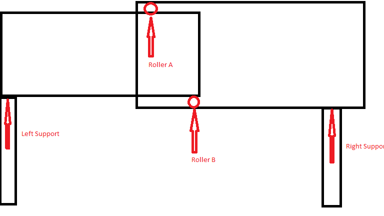
I wanted some clarification for how would the reaction loads at end supports and joint will be calculated in the case shown in the schematic diagram. The load of right structure would be supported by roller A however that load would also be transmitted to roller B. In this for value we can just assume that the uniform distributed load of the structure is 30 kg/m2 and distance horizontal distance between rollers is 1m. Thanks in advance.
structure_yvzjdh.png
 
Replies continue below

Recommended for you

retired13,
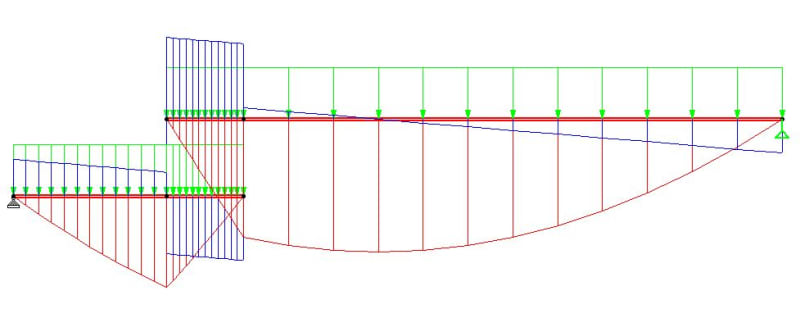
Yes, they are corresponding to the same loading scheme. Something "suspicious"? Here is the sketch with everything: load, shear, and moment (for clarity beams are shown further apart).

Capture_oqhxsl.jpg
 
Truss,

Strictly to say there are 4 unknowns, Ra, Rb, P1 & P2, if the center of the rollers does not coincident with the beam, then all 4 has different magnitude.
 
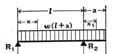
Here is a simple statics exact solution for the forces at R[sub]a[/sub] and R[sub]b[/sub], and I have added a cantilever:

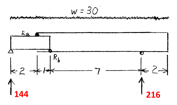
1) Since forces at R[sub]a[/sub] and R[sub]b[/sub] are internal, the "assembled" mechanism is a simple beam with an overhang:

Overhanging_Beam-400_jydoij.png


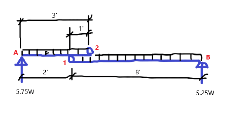
2) Calculate the forces at the supports (Results: 144 and 216).

TB-Assembled-600_odayr6.png


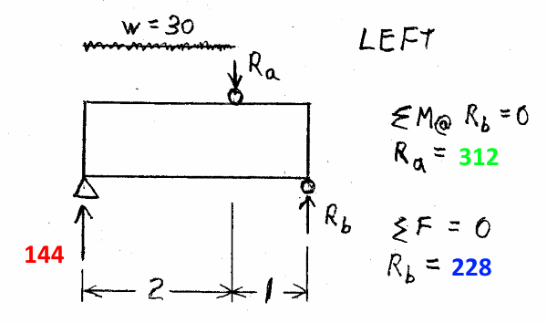
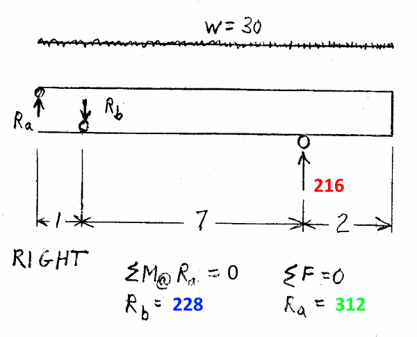
3) "Disassemble" the beam and consider only the left portion. Sum moments to calculate R[sub]a[/sub] = 312. Sum forces to calculate R[sub]b[/sub] = 228.

TB-Disassembled-Left-600_gsn1vi.png


4) As a check, consider only the right portion of the beam. Sum moments to calculate R[sub]b[/sub] = 228. Sum forces to calculate R[sub]a[/sub] = 312.

TB-Disassembled-Right-600_zketln.png


5) "Reassemble" beam, note the following:

Forces at R[sub]a[/sub] and R[sub]b[/sub] on the two parts of the beam cancel each other (as they should).​

Both of the rollers at R[sub]a[/sub] and R[sub]b[/sub] are in compression (as they should be).​

Note: This is a mechanical engineering machine design approach to the problem.

[idea]
 
Who knew that a simple statics problem could stimulate so much discussion?

BA
 
:) I am still in a trauma for not been able to solve this seemly simple problem on a timely manner. Well, blame the COVID-19 that has side tracked my attention :)
 
That same internal couple condition (points/rollers A & B) exists on many different telescoping machine elements, maybe most notably on telescoping crane booms. The trick is to minimize the boom length (lever arm length) btwn. two sets of rollers and still end up with tolerable internal bearing reactions and stresses. The roller systems used to be adjustable cam rollers on hardened stl. wear tracks/plates. Now, many of the bearings are frictionless wear blocks running on smooth bearing plate tracks, with periodic shim adjustments for bearing block wear. These latter are much cleaner than stl. rollers which needed grease and attracted dust and grit, a general mess. Note that on the jetway, the cantilevered end, nearest the plane, does a lot to reduce the internal bearing reaction loads back at the sliding region of the jetway, and keeps the running gear away from the plane. One of the last large designs I used the plastic bearing blocks on was the design for a large under bridge, truck mounted, inspection boom system. There are several fairly elegant developments of this beam problem in this thread, which I want to study a little further.
 
Truss,

Appreciate your help. I was confused on Ra and Rb, didn't realize they are the internal reactions.
 
@SRE,

not so exact … as you've put roller A and B as fixed supports, when really I think they are on flexible supports.

Now assuming these to be rigid simple supports is a valid (practical) simplification, just not "exact".

Now, how many dancing angels can we get on the head of this needle ?

another day in paradise, or is paradise one day closer ?
 
I got a balanced system by simply take moments about support points A & B without consider forces on the rollers/pins. ΣFy and ΣM are both satisfied, however, I think this solution does not seem right, as force on the rollers/pins equals zero, when taking moment about point 1 & 2 respectively.

Link

Seems the "Upload function" is messed up again.
 
rb1957 - Good point. As someone who used a slide rule, I should never have used such "exact" wording.
I'll make an edit to that post, with a nod to XR250 and BAretired who, several days ago, noted that solution did not have to be "difficult".

[idea]
 
Upload works for me.
OverlapTruss_osj0zm.png


retired13,
You did precisely the right thing by solving for reactions as you would for any beam. The external reactions are independent of the shape of the member. Reactions at points 1 and 2 have to be calculated based on the equilibrium of either member.

Your wood model with the two nails provided a moment connection to prevent collapse, but the nail reaction did not affect the load going to each end.

BA
 
BA,

Thanks, you are correct. The internal forces cancel out. What a lesson! Salute to people who have recognized and solved this "simple" problem in no time.
 
You need to understand the problem correctly and draw the structure, loading and supports correctly as well. The diagram that you presented does not represent original question.

The structure on the wheeled support (right end support) is almost balanced by the loads on both sides. One side on this structure attached on the other by upper and lover rollers (A and B) which provide sliding. Other structure is cantilever with moment connection on left end support. Both structures are connected with sliding support (roller A and B). Therefore the system is stable for this reason.

When right end moves the system slides the bending moment changes on the left end support.

Hope this clarifies everything.
 
saplanti,

This is a long thread, I don't blame your jump into conclusion without read through the posts, and see all sketches. Anyway, if you don't mind, can you share your sketch with us, as word alone can be misunderstood. Thanks.
 
TrussBridgeboy:
The bearing reactions don’t change too much on the jetway. The outer end canti. and its long back span over the running gear pretty much control the structure and the bearing forces/stresses. While the lever arm btwn. the two sets of bearings doesn’t change too much in proportion to the long main span and its canti., due to limited longitudinal length adjustability. On the other hand, with a crane boom, the canti. lengths of the boom tip sections change radically with respective lever arm lengths btwn. their back bearing points; going from essentially a zero canti. length, and large lever arm btwn. the support bearings, to a long canti. length and a very small lever arm btwn. the support/back bearings. Then, you add the lifted load and dynamic action to the boom tip when working. These bearing forces can literally open/unzip the boom end of the back/supporting boom section like a sardine can.
 
Yeah dhengr, it even looks a bit like an old fashioned can opener when the boom is out as far as it can go. Lots of prying action.

BA
 
retired13

My comments did not target your posts. But I forget to put the originator in my post. I apoligise it seems I targetted you.

The photograph of the jetway speeks all the story, and is the diagram of the structure. The originator probably does not have structural background and does not know how the jetway functions.
 
saplanti,

Never mind. I only wonder if you have other idea that may add more fun into this thread.
 
BA,

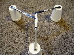
I think you are the lead solver here:) any thinking about Tomfh's knife bridge?
 
Status
Not open for further replies.

Part and Inventory Search

Sponsor