Eng-Tips is the largest engineering community on the Internet

Intelligent Work Forums for Engineering Professionals

Reading camber table from engineering drawings?

Status
Not open for further replies.

Daniel5033

Structural
Jun 3, 2020
9
0
0
US
Dear Friends

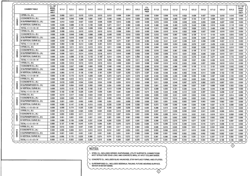
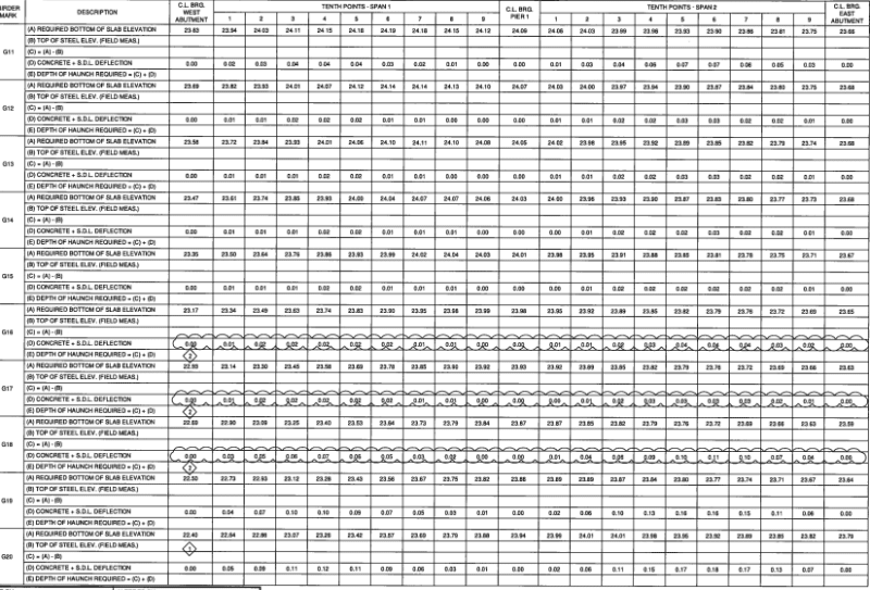
I am a structure detailer and i looking to move forward to detaing steel bridge but i having problem getting the camber or reading the camber diagram table from the engineering drawings, i been trying to contact steel bridge detailer but they dont replay back or want to help, i hope someone could help me, i will really appreciate thank you.
 
Replies continue below

Recommended for you

Basically a camber diagram breaks the beam into spans and gives the dead load deflection at points indicated along the span, usually 10th points.

The dead load is broken up into different categories of dead load. For a typical bridge you have a few cases:

1. just the steel (I = steel section)
2. weight of the concrete deck + haunch (before the deck is composite) (I = steel section)
3. weight of any concrete (barriers, etc) that are placed after the concrete hardens (I = composite section)
4. any additional architectural camber or vertical cambering required, this isn't a deflection its a precambering to achieve the desired bridge profile or vertical curve.

The example you listed is a bit different than i'm used to seeing. There is no case 3, i guess the rails are being placed along with the deck and no load is being placed after the deck hardens.

This information is useful because the fabricator needs to know how much precamber to build in so when the beam sits under its own weight, it doesn't appear to sag. The contractor also needs to know how much deflection to expect when he places the deck, and after the deck hardens, how much the deflection will occur from barriers. He , for example, need to make sure those to deck sections line up at the longitudinal construction joint.

Fwiw, this is an extremely poorly layed out camber table, im having having a hard time following it. Usually its one big table.
 
I agree with Mike; this is a poor example of camber table. At the DOT where I work, we give a camber diagram for the steel fabricators to do the web cutting for the girders, which accounts for all dead load deflections and the grade profile. We also give screed elevations for the field crew to set the elevations for a 'dry run' of the deck placement. The screed elevations include the same adjustments as the camber diagram, except for the selfweight of the girders, since the girders are erected and deflected due to their own weight, when the screed elevations are checked.

All of this would be calculated in the design, and given to the detailer as the camber and blocking ordinates to be added to the camber diagram, and a finished screed elevation table, with all the elevations in the table.

That said, bridgebuster's markup and notes are about as good as it gets. I don't think I can add anything more that would be helpful.

Rod Smith, P.E., The artist formerly known as HotRod10
 
Thanks Rod.

This is a typical camber table used on NYSDOT projects

ct_v5dk9f.png
 
So it looks like you are checking a shop drawing.

The contract plans are in 10th points, the shop drawing has more. So you need to get do some math and interpolate between the points the contract plans show and the points the fabricator provided.

Otherwise it's pretty straight forward, just add up the total camber on the contract plans and see if the shop drawing matches.

Note you can verify the end cut buy doing a bit of math from the camber value at midpsan. Also the fabricator is welding together two plates, since they cant fabricate from a single plate that is 126' long. Looks like the cut is after the weld so that make it a bit easier. It's never fun reorienting to another reference line.
 
soo all the camber is the total sum of steel dead load, hatch , concrete , rail n etc ?
i been asking to several people one guy told me that there us a form like a excel sheet where you can put all the number and will give you the total sum of all the number idk if is true or no.

ik that steel bridge can be more complicate that structure.
but some times i got confuse because not all the time they show the number in inches sometimes the number are show like 0.305 1.021 and it got me confused.

do u know if there is a book o a pdf file that show or teach everything related to camber or how to detail steel bridge drawings
 
Daniel5033 said:
do u know if there is a book o a pdf file that show or teach everything related to camber or how to detail steel bridge drawings

Try this....

Link

Go to page 13 and 15 of this document. This is what helped me understand how to establish a set of design drawings showing required camber. It's pretty straightforward, but don't forget about the geometric camber. This occurs if your abutments and piers are not at the same elevation and sometimes is shown on the drawings and sometimes is not.

Link

This is also a personal favorite of mine as it helped me better understand how to detail cross frames when the bridge has a geometric crown or superelevation.

Link
 
Status
Not open for further replies.
Back
Top