Continue to Site

Eng-Tips is the largest engineering community on the Internet

Intelligent Work Forums for Engineering Professionals

  • Congratulations SSS148 on being selected by the Eng-Tips community for having the most helpful posts in the forums last week. Way to Go!

Rebar development in concrete walls 1

Status
Not open for further replies.

BAGW

Structural
Jul 15, 2015
392
Hi,

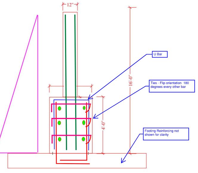
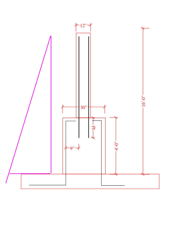
I have cantilever wall with dimensions shown below. When the 12" wall sits on the 30" wall, I am fully developing the rebars in the 12" wall into the 30" wall to transfer the moment. The rebars in the 30" wall are sized to continue the applied moment. My question should the rebar at the 12" wall be spliced with the rebar's of the 30" wall? Technically, the bars cannot be spliced as they are 9" apart (exceeds ACI limits). Will developing the rebars in the 12" wall into 30" wall suffice?

Thanks
Document1_dqi9wd.jpg
 
Replies continue below

Recommended for you

I believe that you should detail a non-contact lap splice. This thread covers this topic quite exhaustively: Link
 
KootK: Thanks for that thread you reference. Very cool stuff. Though scary because I surely have encountered similar enough situations with a rather incomplete mindset. Thank goodness safety factors help designers too!
 
Due to the spacing of the bars in the non contact lap and the fact that this is a "disturbed region", I'd also review an appropriate strut and tie model and detail the reinforcement accordingly (for in-plane and out-of-plane loading). For example a strut and tie for in-plane loading would tell you at the transition that you'll have a horizontal tension tie, whereas you sketch suggests the bars simply terminate with a hook. For out-of-plane loading it would again suggest some horizontal ties being required.

I'd also suggest for practicality in constructing it that you consider the possibility of the upper wall bars simply continuing through as the thickening is only 4' high. Otherwise you're left with a storey high cage levitating in space.

Often detailing requirements would preclude laps near the base of walls. Unsure of the purpose of the wall. But worth reviewing.

Also review the moment coverage to make sure the moment capacity is appropriately developed.

 
What if you did something like this.

As Agent 666 mentioned, this is a 'D-region' where strut & tie would apply.

The moment at the base of the 12" thick stem, needs to transferred to the larger 30" stem.

This is done through shear in the 30" section, so you need to confine the area with ties.

Capture_rdsyq9.jpg
 
Why the hooks at the top... if you need a bar going across, best to use an inverted 'U' bar as Joel shows... it gives a bit of 'adjustability' in the field and the bottom legs should be rotated as Joel shows so they are in the compression area of the blob on top.

Joel: I don't know why the added horiz reinforcing; maybe just the green TS bars, but the intent is quite correct. The OP's tension development length should work... bars extended for support only? Might be difficult in tying large bars to 'U' bars.

Rather than think climate change and the corona virus as science, think of it as the wrath of God. Feel any better?

-Dik
 
Dik Green bars are there to anchor the ties around. They are probably not extra as you'd have horizontal bars anyway.

Good call dik and Joel on turning the bars in the footing inwards. Missed that one.

 
I added the horizontal ties (pink) because I think 6" is the max distance apart you can have a non-contact lap splice, and the OP is at 9".

I like the idea of the ties hugging and confining the concrete at least through the development length of the vertical green bars. The one at the top could be deleted since the horizontal U bar leg would be serving the same purpose.

The light green horizontal bars are just your normal T&S bars, and they also serve as a spot to hang the horizontal pink ties from.
 
I'm partial to Agent666's solution of running the upper wall bars all the way down:

1) Simple
2) Predictable
3) You still get a big bump in flexural depth at the bottom even if it's not the whole thing.
4) You're not relying on the stresses in that wide, short, block of concrete moving around unreasonably quickly.

The footing doesn't really look thick enough to properly mobilize the entire pedestal width anyhow.

C01_lrrbva.jpg
 
Status
Not open for further replies.

Part and Inventory Search

Sponsor