Continue to Site

Eng-Tips is the largest engineering community on the Internet

Intelligent Work Forums for Engineering Professionals

  • Congratulations KootK on being selected by the Eng-Tips community for having the most helpful posts in the forums last week. Way to Go!

Reciprocating Compressor Foundation 3

Status
Not open for further replies.

SouradeepGuha

Structural
Aug 28, 2020
8
Hi,

I was going through the Design of Structures and Foundations for Vibrating Machines by C. Arya and O'Neill.
I found the solved example of a vertical reciprocating compressor fdn but couldn't understand the force direction which should be perpendicular to piston movement. In the attached fig. from the book. Fz is the direction of forces along the piston as it is a vertical compressor.
Now, as the axis of crank shaft and motor is parallel to X axis shouldn't the direction of the perpendicular force be along Fy and not Fx as depicted in the example. No force should be acting along the direction of the shaft.
Is this an errata in the book or am I missing something.
I sincerely apologise if you find the question silly but kindly help.

-Soura

 
 https://files.engineering.com/getfile.aspx?folder=b947f93a-ba97-488b-abc1-9d38d57244b5&file=Machine_fdn.jpg
Replies continue below

Recommended for you

The reciprocating compressor at worked example has 4 cylinders ,and the crank shaft parallel to X axis , so the UNBALANCED FORCE will develop along Y direction. Look to the Vendor data and figure 6-2 , modes of oscillation.
If the crank is parallel to X axis and pistons on vertical Z axis,(with 4 cylinder set up) unbalanced forces will not develop along X axis pitching and rocking moments will..

I will suggest you to look ( FOUNDATIONS FOR INDUSTRIAL MACHINES Handbook for Practising Engineers by K.G. BHATIA ) to see the concept.
 
Thanks @HTURKAK for the help. Ill definitely look for the book.
For a single piston I understand the forces are along the piston and another perpendicular to the piston, but none along the crank shaft axis.
In this case the unbalanced forces are acting in the direction of crank axis because its a 4 cylinder compressor? Does the no. of cylinders changes the unbalance force directions? Below is the image for a single cylinder reciprocating machine.
Just to be on same page axis I understand that the crank shaft refers to the axis about which the crank throw rotates. In the fig below crank shaft axis is the global X axis.

Thanks in advance!!

image_m1hc46.png
 
For a structural engineer you are way overthinking this.
Choice 1: Design a solid foundation an be done with it. Unless this is a compressor the size of a house then you are wasting your time.
Choice 2: If it is a massive compressor then talk to the supplier they will know much more about the dynamic forces than any book or equation will tell you.
Choice 3: Spend a long time researching reciprocating engine balancing which might be fun but entirely useless. Return to choice 1 or 2.

 
I was going through the Design of Structures and Foundations for Vibrating Machines by C. Arya and O'Neill.
I found the solved example of a vertical reciprocating compressor fdn but couldn't understand the force direction which should be perpendicular to piston movement. In the attached fig. from the book. Fz is the direction of forces along the piston as it is a vertical compressor.
Now, as the axis of crank shaft and motor is parallel to X axis shouldn't the direction of the perpendicular force be along Fy and not Fx as depicted in the example. No force should be acting along the direction of the shaft.

Looking in the book, I don't see how you would know (either way) whether the force is oriented correctly: not enough info is given. In the problem statement (on p.93), the info is given as if from a vendor. Nothing appears odd about it.
 
I got internet access problem and just see your respond.
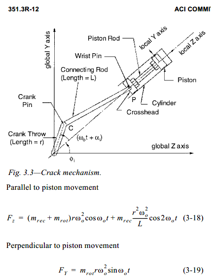
The picture that you posted a snap from ACI 351.3R .. the forces for the single piston will develop along local Z axis and local Y axis ( Perpendicular to piston movement ).


In case of multi cylinders , the dynamic forces shall be computed similar with single cylinder machine but the net
force developing on a specific direction is the algebraic sum of the force developed in each cylinder in that direction.

The forces are vendor data . In case of data unavailable , you may follow ACI 351 3.7—Method for estimating inertia forces
from multicylinder machines.

I hope this respond makes sense.
 
Thinking about this further....I can kind of see where you are coming from. You'd think that with the unbalanced motor force being in one direction horizontally (as shown on p.95 of Arya and O'Neill's book).....the (horizontal) unbalanced compressor force would be in that same direction. (Based on how you would expect the motor to hook up to the compressor.)

But this is a fictional problem. (As far as I can tell.) Maybe they just want to demonstrate (pictorially) the notion of rocking about both orthogonal axis. If this is based on a real world problem, they must have used some sort of gear box to make it happen. (But then things wouldn't quite line up like they do here.)

So the bottom line is: it's good to note.....but not much to worry about. (Since it appears you are doing this as some sort of exercise.)
 
Thanks to all for your replies!!
I too had the same notion as @WARose that this is a fictional problem or the use of a gear box.
Yes this is sort of exercise. I'm about to design a compressor but my lead advised me to go through this book and understand all the requisites of designing the foundation.
The links by @human909 were fun to read, but yes as a structural engineer I too would prefer to go for Option 1 and 2!!

Cheers...

 
Status
Not open for further replies.

Part and Inventory Search

Sponsor