Continue to Site

Eng-Tips is the largest engineering community on the Internet

Intelligent Work Forums for Engineering Professionals

  • Congratulations KootK on being selected by the Eng-Tips community for having the most helpful posts in the forums last week. Way to Go!

Recirculation Pump for Water Tank

Status
Not open for further replies.

Jack Benson

Industrial
Jul 11, 2023
101
I have posted about this system before, but not specifically the problem i am posting about now.

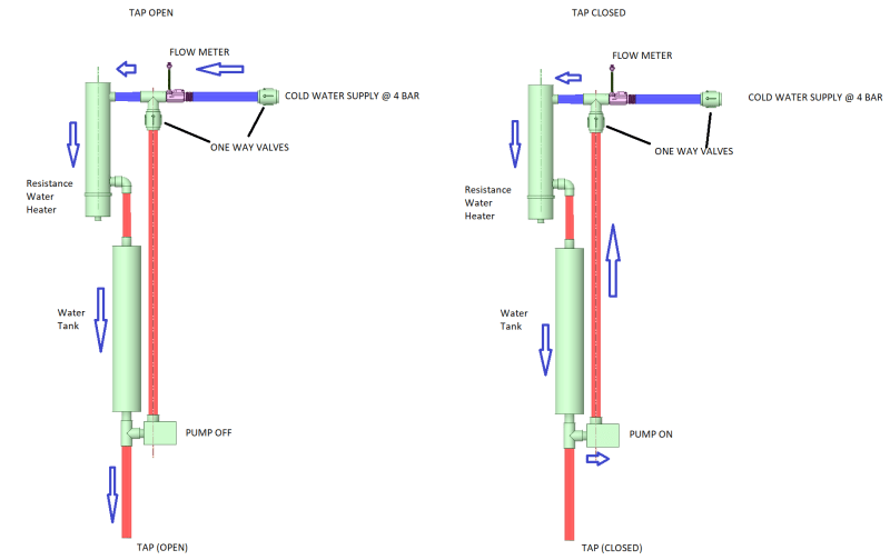
We have a small instant water heater that has a small water thank (1 litre) attached to it.

The water heater is has a volume of about 0.5 litres.

Its for a very specific application.

When we need to use the warm (not hot max 40C) from this system, we press a button that starts a pre-heat cycle where the water heater comes on and a small pump starts, and heats all the water in the water tank and the water heater to 40C.

There are temp sensors to cut the power off to the water heater when ready.

This is the schematic of our system that i have posted before when asking about where to position the flow sensor:
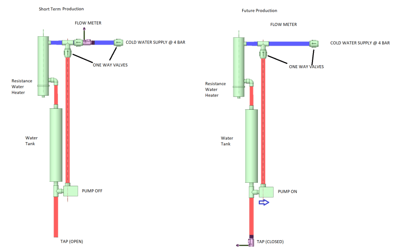
Recirculation_Pump_Diagram_With_Flow_Meter_-_Copy_rustvv.png


I very very nervous about choosing a pump that would be ok.

We were looking for something 12v, about 20 watts, as we had tested with this power level and it was adequate for our needs.


I was discussing with various suppliers in China and settled on this pump after lengthy discussions with them (they did pressure tests / temp tests for me).
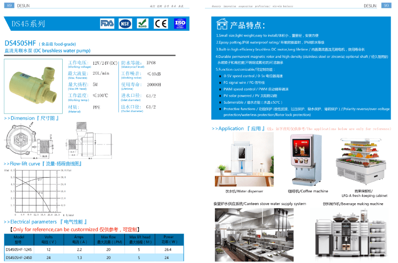
Desun_DS4505HF_ybhisa.png


This is a link to the full manual: Link


We got the delivery about a month ago, and it was working well in our test environment.


This week we got a new sample PCB and instead of the temperature maxing out at before 40C, it was going to about 45C. This is a bug that will be fixed.


The problem was that the pump developed a leak on one of the screw threads (see video): Link


I found it very difficult to source this part and it was the item that i was most worried about when sourcing.

I was able to find something suitable in the EU market to benchmark the specification.


I do not know if the issue here is the water pressure (max 4-bar) or the increase in temperature or that that the pump is just not suitable for our application (which i worry is the most probable).

I realised that I do not have the specific material the pump is made from in my file so I have asked for the information.


I should be able to limit the pre-heat temp to 35 C but i do not want to have a part that is prone to failure in the system.


Your insight is always appreciated.
 
Replies continue below

Recommended for you

It needs an expansion chamber. Typical water heaters allow expansion back into the supply line but that path is blocked off here. There should also be a pressure relief valve with the check valves.
 
the diagram is a simplification of the system. the water tank and water heater are not directly connected. There are other components in between.

the pump circulates the water everywhere in the system

Convection will not circulate the water quickly enough for our needs.

If it were possible to just have a larger tank where the heating element was - i would have done that - removing the problem is always better than fixing the problem.

This company did send me this test report for pressure testing. Like you i questioned why they did not state the static pressure on the spec sheet for the product:
I will research peristaltic pumps
 
thank-you 3DDave.

I wonder if the increase in pressure in the system could have caused the pumps failure.

In standby, the water in the system will be at whatever the network water temperature is (between 7-22 C depending on the time of year) [There will be some warming based on room temperature depending on how long the system is left in standby mode].

The system has a preheat mode that is entered into while the tap is closed.

This means that the approx. 3 litres of water in the system was heated to the target temp which was approx. 43C at the time of the pumps failure.

There would have been a rise in pressure in the closed system as the temperate would have risen by approx. 20 C.

As it has been pointed out, there is a one way valve preventing some of the pressure being relived into the pipework.

I would like to work out what the pressure rise would have been.
On Monday we will test this will a pressure gauge.

Recirculation_Pump_Diagram_With_Flow_Meter_el2trq.png
 
It's about 2 bar per C.

Relief of even a few drops in that amount of water would relieve the pressure, but yes, you need to install a pressure relief valve or an expanding tank or both rather than have the weakest part of the system do it for you.

Remember - More details = better answers
Also: If you get a response it's polite to respond to it.
 
I think 3DDave is right about needing a small expansion vessel. With a shut-in section subject to temperature changes, you ought to have a relief valve somewhere downstream of the inlet one-way valve as well.

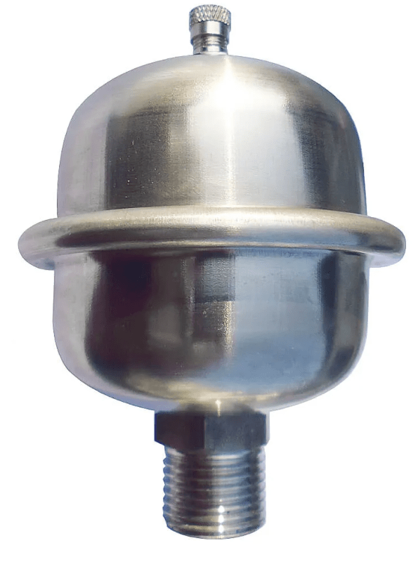
Trying to calculate the pressure rise is a fool's errand. That will depend too much on the elasticity of the pipework and other components, with compressibility of the water just adding to the confusion. Work out the increase in volume and use that to size an expansion vessel. A 10 bar rated, 2 litre expansion vessel suitable for potable water should be available off the shelf from your local plumbing supplier for around 30 Euros. Much smaller (0.16 litre) units are also available at broadly similar prices.

I saw a broadly similar hot water system the other day - one where somebody has helpfully included two ridiculously large, 207 bar working pressure hydraulic accumulators into the circuit. I feel the overkill solution there may be a sign of how frustrated they were getting beforehand.

A.

(Addon: I was still typing when LittleInch posted)
 
LittleInch Thank-you

zeusfaber - i agree trying to work out the exact number is pointless. I was more trying to work out if this could be the cause of the pumps failure.

Whatever the outcome we will add a pressure release valve

Most of the pipework is EPDM flexible hoses that will have a level of flexibility.

I will measure the pressure rise on Monday during preheating.

I will look into a small expansion vessel

Thank-you
 
I went though the log files saved from our test environment and found that at the point that the pump failed, the temperature in the system had risen from 21C to 56C - a 35C temp rise.

There was a bug in the test firmware in the PCB that did not prevent the overheating.

The system has a solenoid valve that I can programmatically open momentarily to release pressure from the system as the temperature rises, although a pressure release valve is the safest options as it does not rely on the PCB.

I am looking at options to manage the expansion.

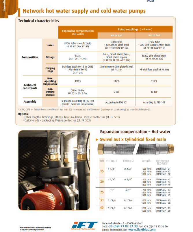
I have seen these textile braided hoses that appear to be designed too expand as water heats up.

Ezyflex_gtq7kn.png


This article gives a rate of expansion of water is 1.000208 per 1C rise in water above 4C

In the error state the system was in, with a 35C temp rise, if the article and my maths are correct, the expansion would have been 1.007305801.

For 3 litres of water this would mean 21 ml.

Can someone confirm if this this correct?

In normal operation, the max temp rise should be 7C to 35C = 28C

thank-you for everyone's help


C Temp Rise Expansion / C Total Expansion
1 1.000208 1.000208
2 1.000208 1.000416043
3 1.000208 1.00062413
4 1.000208 1.00083226
5 1.000208 1.001040433
6 1.000208 1.001248649
7 1.000208 1.001456909
8 1.000208 1.001665212
9 1.000208 1.001873558
10 1.000208 1.002081948
11 1.000208 1.002290381
12 1.000208 1.002498857
13 1.000208 1.002707377
14 1.000208 1.00291594
15 1.000208 1.003124547
16 1.000208 1.003333197
17 1.000208 1.00354189
18 1.000208 1.003750627
19 1.000208 1.003959407
20 1.000208 1.00416823
21 1.000208 1.004377097
22 1.000208 1.004586008
23 1.000208 1.004794962
24 1.000208 1.005003959
25 1.000208 1.005213
26 1.000208 1.005422084
27 1.000208 1.005631212
28 1.000208 1.005840383
29 1.000208 1.006049598
30 1.000208 1.006258856
31 1.000208 1.006468158
32 1.000208 1.006677504
33 1.000208 1.006886893
34 1.000208 1.007096325
35 1.000208 1.007305801
36 1.000208 1.007515321
37 1.000208 1.007724884
38 1.000208 1.007934491
39 1.000208 1.008144141
40 1.000208 1.008353835
41 1.000208 1.008563573
42 1.000208 1.008773354
43 1.000208 1.008983179
44 1.000208 1.009193047
45 1.000208 1.009402959
46 1.000208 1.009612915
47 1.000208 1.009822915
48 1.000208 1.010032958
49 1.000208 1.010243045
50 1.000208 1.010453175
51 1.000208 1.010663349
52 1.000208 1.010873567
53 1.000208 1.011083829
54 1.000208 1.011294135
55 1.000208 1.011504484
56 1.000208 1.011714877
57 1.000208 1.011925313
58 1.000208 1.012135794
59 1.000208 1.012346318
60 1.000208 1.012556886
61 1.000208 1.012767498
62 1.000208 1.012978154
63 1.000208 1.013188853
64 1.000208 1.013399596
65 1.000208 1.013610383
66 1.000208 1.013821214
67 1.000208 1.014032089
68 1.000208 1.014243008
69 1.000208 1.01445397
70 1.000208 1.014664977
71 1.000208 1.014876027
72 1.000208 1.015087121
73 1.000208 1.01529826
74 1.000208 1.015509442
75 1.000208 1.015720668
76 1.000208 1.015931937
 
Seems about right

The volume is small but as the Bulk modulus is very large the pressure rise can be significant.

The pipes may well be limiting the pressure rise as they expand, but it will be higher than your static pressure and providing an expansion vessel or relief valve is required. Problem with a relief valve is that it now needs a drain....

Remember - More details = better answers
Also: If you get a response it's polite to respond to it.
 
I understand that the increase in pressure would be significant. I am not trying to argue it.

I was wondering if by adding a specific type of flexible hose that is designed to expand when the water expands due to being heated it could be a solution (but you are right - the pressure would rise above the static pressure level).

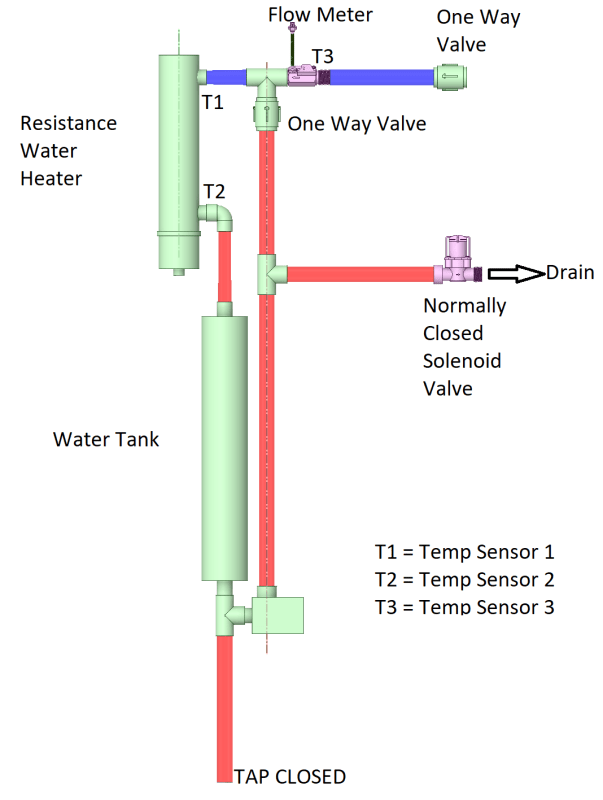
In the circuit, there is a normally closed solenoid valve that connects directly to the drain.

It would be possible to open it momentarily [every few degree temperature rise] to relieve the pressure.

We will do some testing to see how much the pressure rises per degree and go from there.

Recirculation_Pump_Diagram_With_Flow_Meter_and_Solenoid_Valve_avo4pv.png
 
Having both is most likely to lead to trouble-free operation.

The expansion vessel will prevent the relief from lifting all the time and save you wondering when it will eventually fail to reseat.

The Relief will save your pump when the expansion vessel loses all its gas charge.

A.
 
Yes

Remember - More details = better answers
Also: If you get a response it's polite to respond to it.
 
We ran the test this morning.

We increased the temp in the closed system from 20 C to 40 C.

There was a maximum 0.2 bar rise in pressure.

my best guess is that the flexible pipes in our system absorbed the expansion.

This is a Video of the test. At 1 min 37 sec we open the tap and the pressure drops to 2.4 bar.


The only unusual factor we have now at the time of the pump failure was that the water temperature increased to 56C instead of the usual maximum of 40C.
 
thank-you to everyone who has contributed to this thread.

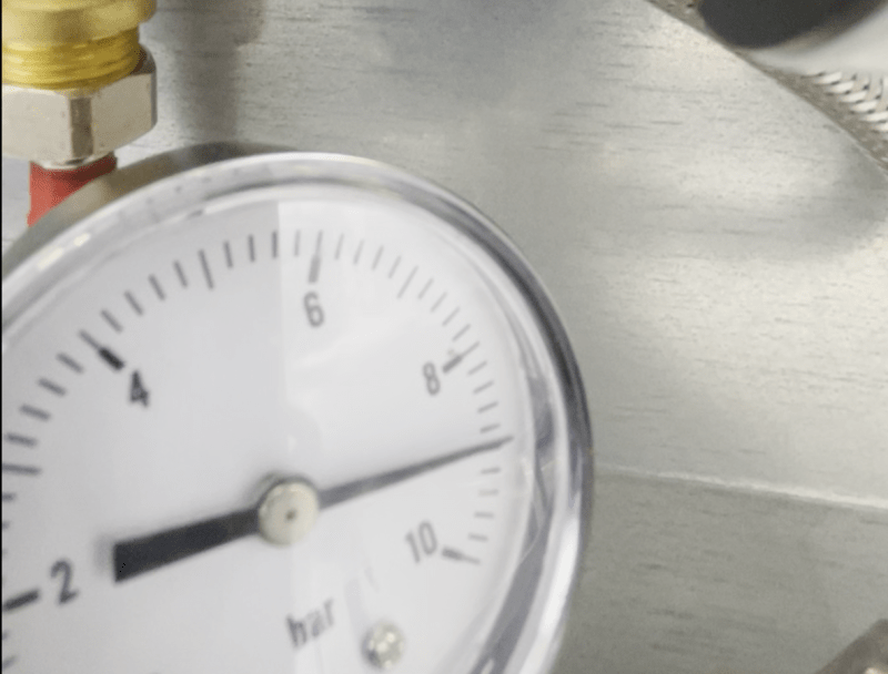
we ran the pressure test again, and it hit 9-bar [an increase of 6-bar]:

9_bar_zrak1y.png


we must have not set up the pressure gauges properly in the first test that did not show a pressure rise

An expansion vessel & release valve should solve this issue as recommended.


The water in the system was about 21 C before the heating element as turned on.

This is the video of the test.

When the video starts, the pressure is already 3.7 bar from the 3-bar that was the pressure before heating started.

We then warm the water to 43 C

The pressure peaks at 9-bar at around 3 min 18 seconds

The pressure then drops off (the temp of the water in the system is maintained but not increased.

After 16 minutes, the pressure has dropped back to 6.4 bar

The tap remained closed thoguhtout.

I would not have found this without your help.

It is very much appreciated.
 
Lots of reasons why the previous test was different. Even a small amount of air somewhere would make a difference or any leakage past any of the valves.

Expansion tank will make life better for sure.

Remember - More details = better answers
Also: If you get a response it's polite to respond to it.
 
Hello everyone,

thanks for your help with this post.

the mini expansion vessel has solved the issue

We are also installing a pressure release valve.

I would prefer to just install the pressure release valve and not the pressure vessel.

is it advisable?


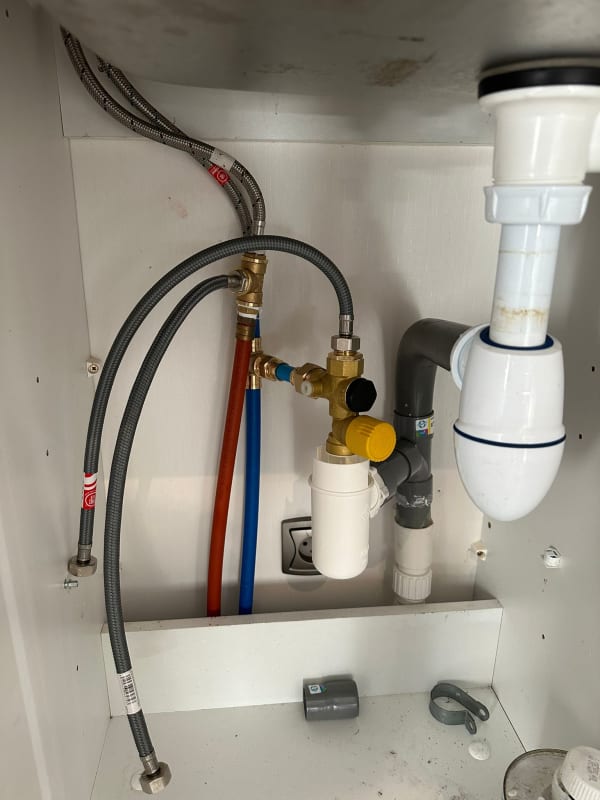
In France i see a lot of instant water heaters that only have the pressure release valve to manage excess pressure in the system:

WhatsApp_Image_2023-11-29_at_12.59.49_1be742b9_jz172x.jpg


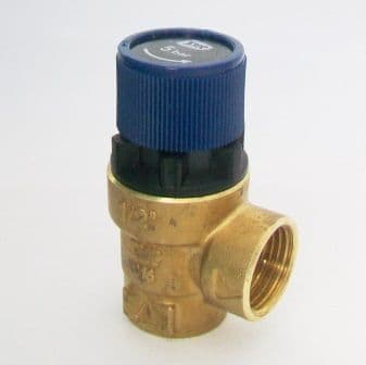
Can i use a standard 5 bar pressure release valve that i can easily plumb into my system:

5-bar-water-pressure-relief-valve-1-2-in-x-1-2-in-07000013-5073-p_myccbx.jpg


my system has access to the waste pipes.

thank-you
 
reading this again I think you already have the answers.

apart from 15th Oct "Problem with a relief valve is that it now needs a drain...." compared to today "my system has access to the waste pipes."

as Zuesfaber says "The expansion vessel will prevent the relief from lifting all the time and save you wondering when it will eventually fail to reseat."

These little relief valves are not intended to work regularly and after a few operations will not reseat and drip continuously or just fail. Also your set point needs to be at least 25% higher than your highest normal operating pressure to prevent weeping.

Probably more so your pressure will vary a lot more than using an expansion vessel.

Not to mention finally "the mini expansion vessel has solved the issue" If it ain't broke don't fix it comes to mind....

Remember - More details = better answers
Also: If you get a response it's polite to respond to it.
 
Status
Not open for further replies.

Part and Inventory Search

Sponsor