Continue to Site

Eng-Tips is the largest engineering community on the Internet

Intelligent Work Forums for Engineering Professionals

  • Congratulations pierreick on being selected by the Eng-Tips community for having the most helpful posts in the forums last week. Way to Go!

Recommended MAWP for a controlled pressure separator vessel 8

Status
Not open for further replies.

aegis4048

Petroleum
Apr 23, 2024
36
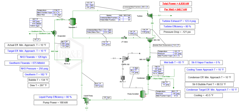
Hi, I have a pressurized 80% ammonia/20% water stream @300 psig/180F. Fluid is pressurized with a liquid pump (it's condensed before entering the pump) that we can fully control, so we expect to be able to maintain a stable pressure on the fluid (we don't expect any pressure swings). Also the system is closed loop, I don't think we will ever expect a surge. The pressurized stream is two phase (approx. 50%/50% vapor/liquid) at the 2-phase separator inlet.

So the normal operating condition for my separator is around 300 psig, and we don't expect this to fluctuate too much. I need to submit RFQ for separator design to manufacturers, and also design a relief valve system. I have a software that can do separator sizing, but by default it sets the MAWP as my operating condition.

Q1. What should I give to the manufacturers for MAWP? (If your answer is "depends", please give some detailed examples).
Q2. What's the difference among operating P, design P, and MAWP?
Q3. I'm thinking of setting a spring relief valve at 10% higher MAWP, and a rupture disk at 21% higher MAWP. Am I doing this correctly?

This is my first time ever doing an equipment design, any help is greatly appreciated.
 
Replies continue below

Recommended for you

P&I D or PFD required which shows control loops, including both upstream and downstream of this 2 phase sep.
Looks like you have some heater downstream of this pump which vaporises this liquid stream into 2 phase at 300psig to 180degF. What is the heating medium and max operating pressure / MAWP of this heating medium ?
 
@georgeverghese

The heating medium is a geothermal water (closed loop). I have a heat exchanger that vaporizes the 80/20 ammonia/water fluid with the hot geothermal water downstream of the pump. Roughly 50% of the ammonia/water fluid vaporizes, while the other 50% remains as liquid. The heating medium indirectly exchanges heat with the ammonia working fluid inside the HX

Imo the pressure of the heating medium shouldn't matter because it matters for the heat exchanger, but I'm interested in the separator downstream of the heat exchanger. The operating pressure of the geothermal fluid is 100~150 psig.
 
A1 MAWP has always been being a challenging point as this is a result of some compromise between the cost of an overpressure protection and relief system and the cost of a system it protects. You should compare the total cost of 3-4 MAWP cases and choose the optimum one. The lowest limit of MAWP is operating pressure + PSV simmering pressure, the highest one - the self-limiting pressure (if applicable).
A2 What is the desgn code?
A3 Incorrectly.
 
IMO, here are the points for reference,
1. Check with Process Engineer for the operation and design conditions. If no design condition, add the operation pressure with 10 to 20 psi to the vessel vendor

2. Have vendor to design the vessel and provide the proper vessel MAWP accordingly

3. The max PSV set pressure should be at MAWP. Depending on the PSV valve type, the valve will be popped at 10% over the set pressure.
 
It does "depend"... typically this includes

What the process pressure can reasonably achieve in "normal" operation. This includes stop / start, heat up / expansion/ process control of the pressure ( seems to be your fluid pump), and then a number of fault scenarios.

So typically blocked outlet of the separator - what can you pump produce at dead head with highest inlet pressure?
What pressure can be produced if your heat input increase to it maximum amount?

A PFD or P&ID of this system would be good and may raise some other issues

If there is any sort of pressure control or pressure trip, be it a single HH pressure or a 2oo3, this is typically set 8 to 10% below your MAWP and usually with sufficient clearance over your operating pressure to avoid spurious trips or alarms, so again typically 5 to 10% for a relatively steady state operation.

You don't say what design code your vessel is, but they all pretty much set the set point of your pressure relief to the MAWP. There is an allowance of 10% of maximum lift of the relief valve. Note that depending on your relief valve type, the valve may start to pen at 8-10% BELOW the set point with pilot operated ones about 3% below.

Why a rupture disc?
They are usually set again at MAWP, but only used where a relief valve could become overwhelmed or unable to act fast enough by a very sudden very high gas release into the PV, usually something like a tube rupture on a Shell and tube HX. Rupture discs are a failure waiting to happen by design and don't close or reset once the pressure decays. Ammonia is a pretty nasty substance so you need to be very careful about suddenly releasing very large volumes into the air. So for me a rupture disc won't really work as you can't pipe these very far from the vessel and need HUGE vent pipes to cope with the gas flow. Ditto your Rrelief valve discharge will need somewhere to go that doesn't kill anyone.

IMHO, you really do need someone to guide you here local to you, not a bunch of strangers on the internet. DO you have no company guidelines or mentors?

But here's your questions
Q1. What should I give to the manufacturers for MAWP? (If your answer is "depends", please give some detailed examples). See above. But more than the max operating pressure for sure.

Q2. What's the difference among operating P, design P, and MAWP?
Operating pressure is the pressure it operates at
Design pressure is what you set the design pressure of the whole system, not just the PV and is usually the Max operating pressure plus a bit to allow for trips, alarms and relief valve setting. It is what you should be telling the PV designer as well. This sets all your flange ratings, pipe thicknesses, instrument design pressure etc
MAWP for a PV is actually reverse calculated once they've done the design as many items have minimum thicknesses or step changes in thickness etc. So MAWP of a PV can be the same or often higher than the Design Pressure. a bit odd, but that's the way it works.

Q3. I'm thinking of setting a spring relief valve at 10% higher MAWP, and a rupture disk at 21% higher MAWP. Am I doing this correctly?
NO
See above.
You CANNOT set relief devices higher than the MAWP or Design pressure for anything other than the PV.


Remember - More details = better answers
Also: If you get a response it's polite to respond to it.
 
@georgeverghese
image_dwye5z.png

The attached is my PFD. I'm the process engineer (entry-junior level) that designed this. The PFD describes a kalina cycle (meaning that it uses ammonia/water mixture as working fluid) geothermal plant. I do not have a P&ID. I am tasked with learning & designing P&ID, but I barely have any experience with it. I have decent experience with process sim tho. My employer wants me to learn P&ID so I can grow more into that field. The plan is to have me learn & design a preliminary P&ID and hire an experienced P&ID consultant and have him check my work.

@shvet
Thanks, I think that's a good idea. I will ask the manufacturers to give me quotes for 350, 400, and 500 psig MAWP scenarios.

@mk3223
Thanks, please check below if possible

@LittleInch
Regarding your comment about liquid pump, is it a good practice to determine a maximum "operating" pressure based on the dead head liquid pump pressure in my scenario then? There's a HX between the separator and the liquid pump. Where do you think is the best to put PRV and PSV then? Also your comment that I should give the design P for PV sizing clarifies a lot.

@all
I've read yall's comments, and done some readings on my own. Here's what I've learned.

1) To request quote for PSV, PRV, and separators, I should give the manufacturers my max operating P. My understanding is that max operating P = design P.
2) The typical operating P is 280 psig, but I make an engineering call that the max operating P can go upto 350 psig. This is what I give to the manufacturers for RFQ.
3) The manufacturers will return to me with a quote for MAWP. Let's assume that they gave me MAWP = 500 psig.

Now there's the parts that I'm not too sure...

a) I'm reading 10% allowance for PRVs or PSVs, and 21% for fire case. I'm not sure what these values are based at. Is it 10% over the max "operating" pressure(=350 psig) or max "allowable" P (=500 psig)? At what pressure should I set my valves for the 10% allowance?
b) Is it recommended that I set 2 valves for overpressure and fire case scenarios? I'm reading that I should set firecase PSV at 21% higher than MAWP... but the people here are saying that the PRV or PSV should never exceed MAWP, so this is really confusing.
c) Should I set both PRV and PSV, is either one of them fine?

Thanks for all your help, folks. Please comment if there's any advice you could give me.
 
aegis said:
I'm reading 10% allowance for PRVs or PSVs, and 21% for fire case. I'm not sure what these values are based at. ... I'm reading that I should set firecase PSV at 21% higher than MAWP... but the people here are saying that the PRV or PSV should never exceed MAWP, so this is really confusing.
 
you should set the Design pressure correctly as we've all been telling you - this needs to have a margin over the max operating temperature to allow for alarms, trips and variances. This design pressure is used in many places, not just PV design.

Sometimes the PV MAWP will be the same as the design pressure. don't rely on it being higher.

a) I'm reading 10% allowance for PRVs or PSVs, and 21% for fire case. I'm not sure what these values are based at. Is it 10% over the max "operating" pressure(=350 psig) or max "allowable" P (=500 psig)? At what pressure should I set my valves for the 10% allowance?
What this means is that the Pressure relief valves might not be fully open until the pressure has reached 10% over its set point. The setpoint remains design pressure or MAWP. The 21% is for a fire case where the relief flow is higher than "normal" and hence the pressure might rise to allow more gas or liquid to flow through the relief valve. Set point isn't impacted.

b) Is it recommended that I set 2 valves for overpressure and fire case scenarios? I'm reading that I should set firecase PSV at 21% higher than MAWP... but the people here are saying that the PRV or PSV should never exceed MAWP, so this is really confusing.
The SET POINT of the relief valve should not exceed the design pressure or MAWP.
You need to look at the two relief flows for "normal" overpressure and for fire case. If the relief valve which is good enough for the "normal" over pressure case results in a pressure more than 21% over the set point when you ask it to relieve the fire case flows, then you need a separate valve.

c) Should I set both PRV and PSV, is either one of them fine?
Pressure Relief and Pressure safety valve are basically interchangeable terminology. The official title is I think Pressure safety valve, but many people use the two terms interchangeably.

This is a pretty big system!

Location of Relief valves will depend on where you have isolation valves, but yes you need to consider all this.

Remember - More details = better answers
Also: If you get a response it's polite to respond to it.
 
Your simulation says Pop=250psig, but I will use 280psig as you suggest as normal operating pressure. How about this:

Separator pressure-normal = 280psig
Control high pressure = 310psig - suction pressure control high for downstream turbine
High pressure blowoff PIC (backpressure power turbine suction line from gas exit of this sep)to vent setpoint in case of power recovery /backpressure turbine trip = 330psig
High pressure alarm = 360psig
High pressure trip = 390psig - PSV simmer - Max Operating Pressure(MOP) - stop the feed pump and stop heating medium at HX and trip backpressure turbine
Process design pressure = conventional type PSV setpoint = 390 x 1.1 = 430psig

To size PSV, use 10% overpressure for non fire reliefs or 21% overpressure for firecase - check local regulations to confirm


@georgeverghese

wow thanks for a great detailed answer. This really enlightens me on things I haven't thought about. I have a few things that need clarification to understand due to my lack of experience...

1) Control high pressure = 310 psi
Is this the suction control valve setpoint to ensure the fluid pressure entering the turbine is always below 310 psig? So if the pressure is above 310 psig, the valve will choke to reduce pressure to approximately 310 psig?​
2) High Pressure blowoff PIC = 330 psig
I don't understand the purpose of this. Why is there a need to shutdown the turbine because the pressure went up to 330 psig? Is this because you are assuming that the turbine rated for Max 330 psig and that exceeding this limit will damage the turbine? Also, if the suction control valve is working properly, I shouldn't see 330 psig right? So this 330 psig is a secondary safety device?​
3) Would it make sense to devise some bypass system in case of turbine trip, instead of blowoff valve? Because it's probably better to keep that ammonia in the system than venting it to air?
4) Where do you recommend installing the PSV? On a HP separator, HX, or somewhere else?

Looks like the recommendation you gave has 3 stage pressure management: suction control valve, blowoff valve, and then the PSV, and potentially an additional 4th valve for fire case. This level of detail is something I never thought about, really appreciate your insight.
 
1)Yes, you could use this suction control valve to maintain an upper limit to turbine inlet pressure. So this would be a high set PIC sitting on the turbine feed line to throttle the PCV upstream of this PIC. This would be a low dP control valve which is normally full open.
2) This is meant to for some reason where the turbine has accidentally tripped or reduced its speed through its own controls
On second thought, your idea is better to avoid the loss of precious ammonia to the vent. So instead of venting this excess pressure when turbine has dropped out or reduced its speed, it would be better to use this to override the LIC output going to the LCV which would be downstream of the ammonia vaporiser. So feed to this separator would be reduced, backing up level in the source vessel feeding the pump. Level in this source vessel will then rise.
3)See (2)
4)Obviously PSV would be on this separator ? You can use this same PSV for both non fire case and firecase reliefs. It is the permissible overpressure used in the sizing of the PSV that differentiates non fire and firecase reliefs. PSV setpoint remains the same, RELIEVING pressure ( which is set pressure(fixed) + permissible overpressure) which differs for the 2 cases.
 
@georgeverghese

Thanks for your great answers, you nailed pretty much everything I wanted to know & beyond. Tbh I didn't expect to learn this much of detail. Really really appreciate your help.
 
Status
Not open for further replies.

Part and Inventory Search

Sponsor