Continue to Site

Eng-Tips is the largest engineering community on the Internet

Intelligent Work Forums for Engineering Professionals

  • Congratulations KootK on being selected by the Eng-Tips community for having the most helpful posts in the forums last week. Way to Go!

Rectangular Plate bending stress with rectangular slot

Status
Not open for further replies.

Hanson Gill_1983

Mechanical
Aug 16, 2017
21
Dear all,

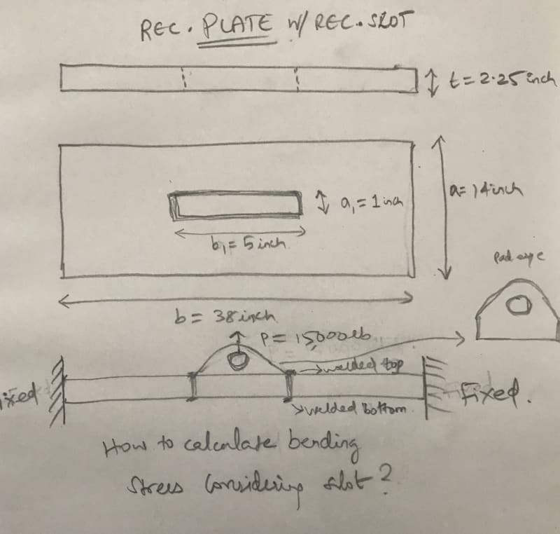
I’m looking to find plates bending stress
as shown in the picture attached.


How to find bending stress at the Centre of the plate considering the rectangular slot as shown?

Plate MYS = 36000 psi

4011F2F5-E4C7-4D27-88BB-5EB88AE5F355_jhqlvz.jpg


Thanks
Hanson
 
Replies continue below

Recommended for you

it is not clear : P=15000 lbs is a point load or a line load ?
 
That is not a slot!

That "slot" is filled with a solid lug that is welded to the horizontal plate.

Now, exactly what is the weld configuration you think you are describing?
That will determine where the load is transferred from the lug's circle to the "top and bottom" of the horizontal plate.

Your note "welded top and bottom" can't work.
I think, based on the solid outline in plan view, that you intend two different welds. A fillet weld on top, welded all-around the lug. However, your side view of the same weld contradicts the plan view.
A plug weld, maybe a full-penetration weld, maybe another fillet weld if the lug sticks through the horizontal plate far enough on the bottom).
Those different weld configurations will change your force description from lug to plate: and thus change your plate bending reactions.
 
engineering practice (not theoretical) :

1 - since you have welding all around the slot, up and down, the slot doesn't exist any more
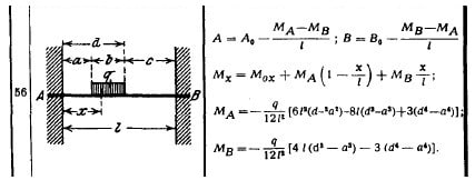
2 - I should calculate as per attached draft where q * b = q * b1 = P = 15000 lbs
3 - use an appropriate safety factor

slotted_plate_nqb4bn.jpg
 
Worse: You have a very small "plate" (38 inches by 14 inches) that is very thick (2.25 inch).

Thus, you don't really have a "simple plate" in any form. How are the two ends "fixed" to the vertical walls? What are the EXACT weld configurations of each end?
How flexible are those "fixed walls"?
(Your assumptions and your "knowns" about the two end conditions will make a significant difference in the reaction of the 2.25 inch plate. In this case, simple thin plate theory is not a good approximation - you need a FEA that is PROPERLY showing the end condition deflections and end condition welds.
 
The plate is bolted four bolts to the right and four to the left. So it’s not felxible.

 
Hanson Gill (OP) said:
The plate is bolted four bolts to the right and four to the left. So it’s not felxible.

No! Absolutely NOT.

The configuration drawn shows both sides "fixed" above and below the horizontal plate. A "fixed" end explicitly forces a certain pattern of bending and moment response in the Rourke book that force the application of specific equations. Use the wrong model of each end, you get the WRONG equations, and you get the WRONG solutions.

That stress and moment configuration drawn CANNOT exist with ANY KIND of bolted connections on the right and left sides.

Bolts are slightly flexible: Even "if" (and that is NOT shown) the four bolts in each end are screwed tightly into 4x horizontal tapped holes in both sides of the 2.5 inch thick horizontal late, that plate will deflect up in the center, will pull away from the wall at the bottom of the plate by a few thousandths, and will bend and compress into the wall at the top when loaded.

That movement will substantially change your theoretical stress model.
Worse, four bolts (in tapped holes on both ends) are very significant stress rise points that greatly change the stress model of your very small plate. Worse, 4x large bolts in a 2.5 inch thick are themselves significant stress risers into a plate at its now "weakest point". Even dowels or welded pins are better than "bolts" in the end when facing shear forces. (By the way, how did you calculate the shear forces across each bolts, and how did you determine a safe bolt diameter?)

Please. Get some help on this, you are not demonstrating the ability to analyze this plate.
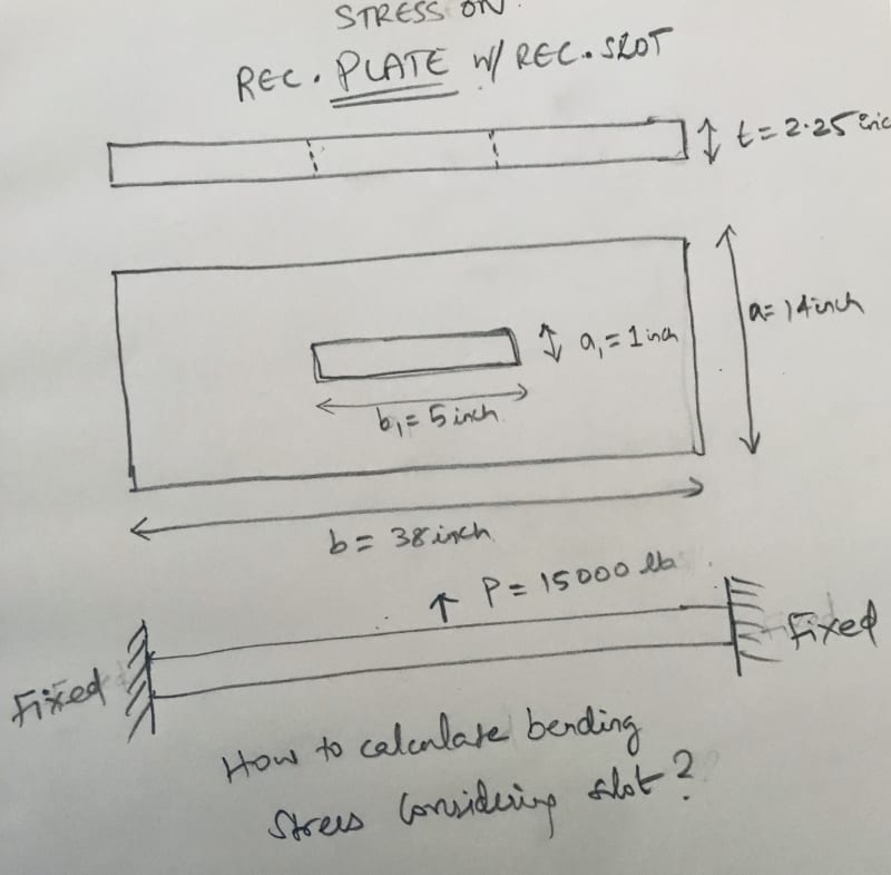
 
thread507-451004 which you posted earlier shows a better picture of the setup.

Why not rotate the pad eye 90[sup]o[/sup] and use a 14" x 38" x ? plate without the cutout for the pad eye; instead, use fillet weld on the two 5" long sides of the eye pad. Forget about end fixity by the bolts. The restraint provided is much less than fully fixed. Consider instead end supports to be hinge and roller. Any restraint provided by the bolts will increase the factor of safety.

Maximum moment M = 15000*(38-1)/4 = 138,750#"

For 14x38x2.25" plate, S = 14(2.25)[sup]2[/sup]/6 = 11.81 in[sup]3[/sup]
Bending stress f[sub]b[/sub] = M/S = 11,750 psi

Depending on safety factor desired, could consider reducing plate thickness.


BA
 
Racook, AISC has plenty of typical fixed all bolted moment connections. Every metal building has fixed bolted connections. It just has to be properly designed.
 
I would weld the pad eye to the top of the plate and not cut a rectangular slot in the steel. I believe I would check it as pinned if I could not guarantee fixity.

I kind of see the attachment to the walls being more of a challenge than the pad eye and plate themselves.
 
Status
Not open for further replies.

Part and Inventory Search

Sponsor