Continue to Site

Eng-Tips is the largest engineering community on the Internet

Intelligent Work Forums for Engineering Professionals

  • Congratulations pierreick on being selected by the Eng-Tips community for having the most helpful posts in the forums last week. Way to Go!

Rectangular tank

Status
Not open for further replies.

cast16

Student
Nov 8, 2020
10
Hi

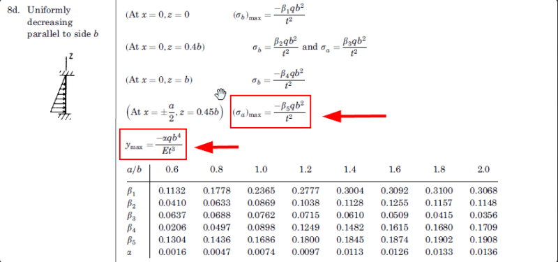
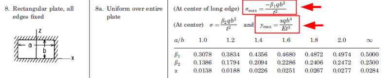
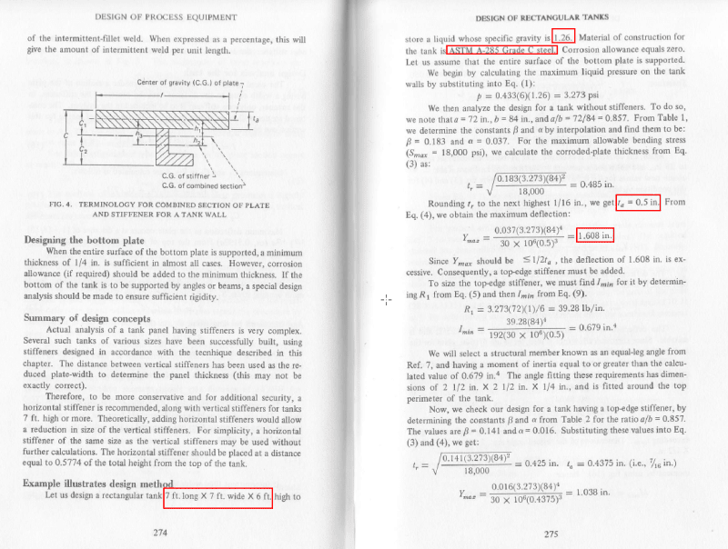
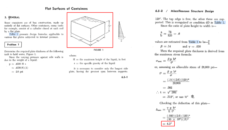
what formula would you use to calculate the deflection and stress on the portion of the tank's wall showing in the screenshot below?
Let assume the tank is full with water, open top and ignore the atmospheric pressure. Material S275 6mm thick
Thanks
2023-04-19_12h16_45_s5emxi.jpg
 
Replies continue below

Recommended for you

Roark is a good source. You can find the underlying reference online too (Moody Rectangular Plates)

If you have to hand calc it ... have the stiffener react the pressure load (from 1/2 bay of side on both sides of the stiffener)

"Hoffen wir mal, dass alles gut geht !"
General Paulus, Nov 1942, outside Stalingrad after the launch of Operation Uranus.
 
Everyone is talking about Roark's formulas.
What is confusing for me: the pressure in this case doesn't start from zero...
Do I have to consider effects of 2 pressures (one constant 14.7 kN/m2 and one increasing to 5.88 kN/m2) and add them together?
Also, is the case of "rectangular plate all edges fixed" most appropriate for this?
Thanks.
 
Roark's book is the best one of this kind and most cases can be found here (in this case, equations for plate bending if you use the approach of treating rectangular pressure walls as separate plates). Of course, sometimes you need to search in different books (like Blevins for dynamics or Peterson for stress concentrations). Here you could also check the book titled "Structural Analysis and Design of Process Equipment" by M.H. Jawad and J.R. Farr.
 
Have you looked at Roark ? (the answer to some of your questions should be apparent).

However if you do you'll realise that you can't easily get to where you want to (Roark is giving the maximum for each loading, and these are not (or probably not) co-incident. Have you tried my search term, which should get you to the reference Roark uses ? This should give you a more general description of the internal stresses. Timoshenko (Plates and Shells) is another reference, but a much harder read.

Why fixed edges ? ... because the edges of the panels are supported by stiffeners. But assuming simply supported edges will probably give a higher (more conservative) result.

If I was doing this (and didn't want to use FE on it), I'd analyze a stiffener (reacting 1/2 a bay of panel on both sides) since the stiffener is the key structural element (reacting the bending from the pressure).

If I had to analyze the panels, I might analyze a strip (1" wide, horizontal and vertical) to see how the panel reacts as a plate in bending. Normally this shows that the deflections are large (compared to the thickness) and so the panel reacts pressure as a membrane (with in-plane forces).

"Hoffen wir mal, dass alles gut geht !"
General Paulus, Nov 1942, outside Stalingrad after the launch of Operation Uranus.
 
IRSTUFF said:
What makes you think those ribs are actually making your "plate" fixed?

I'm just assuming it because the stiffeners are welded to the wall/panel. Correct?
 
rb1957 said:
Have you looked at Roark ? (the answer to some of your questions should be apparent).

I did look. I think the formulas in the screenshot below (case 8d) is the best option. I think I should apply it for the triangular part of the pressure 5.88kN/m2, and the previous formula (second screenshot case 8a) for the continuous pressure 14.7kN/m2. Tell me if I'm wrong.
I want to use the FEA in the future (Nastran in Cad), but would like to be able to check manually if needed.
I have got many of these books, looked at the examples, tested the first one (not stiffened tank) in FEA and the deflection result was very different [ponder]

If you would be so kind as to help, I could share my calculations and FEA results with you in the next days for your review.

2023-04-20_17_00_17-Calcolare_deformazione_e_stress_su_una_porzione_di_parete_di_una_vasca___CAD3D.i_unm3oo.png


2023-04-20_17_08_46-Roark_s_Formulas_For_Stress_And_Strain.pdf_-_Adobe_Acrobat_Reader_32-bit_fudeht.png
 
ok, yes ... you can superimpose these two, but remember they are the maximums for each loading, and may not be coincident but is a conservative approach.
Also similar for simply supported edges (so you can see the difference the boundary condition makes.
You should try to find Roark's reference (a Corps of Engineers report by Moody) ... no, the reference for these is Timoshenko. There you'll find the general expression for stress for these two loads (not just the maximum).

"Hoffen wir mal, dass alles gut geht !"
General Paulus, Nov 1942, outside Stalingrad after the launch of Operation Uranus.
 
I tried to replicate in Nastran the example in the book of Kanti Mahajan(see screenshot). The deflection in the book is around 40mm - in Nastran 7.5mm
2023-04-25_06_57_23-000-vdocuments.mx_design-of-process-equipment-2nd-ed-by-kanti-k-mahajan_-_pg267._afgati.png

Another example from another book (Design_of_Welded_Structures_Omer_W_Blodgett). The deflection in the book is around 110mm - in Nastran 25mm
2023-04-25_07_02_43-Document1_-_Word_dqaqhv.png
 
Status
Not open for further replies.

Part and Inventory Search

Sponsor