Eng-Tips is the largest engineering community on the Internet

Intelligent Work Forums for Engineering Professionals

Redesigning an elevation mechanism, does this make sense? 2

Mizzy07

Aerospace
Oct 18, 2024
1
0
0
CA
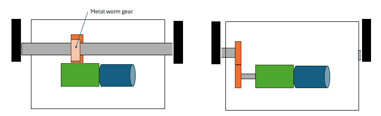
Hi, I'm an aerospace student working on a mechanical project. I'm redesigning an elevation mechanism and would love some guidance. The original transmission system, shown on the left, consists of a blue motor driving a green gearbox that generates the required torque to rotate a metal worm gear that's on the shaft. This shaft rotates two black supports that hold the rotating component.

However, the shaft running through the mechanism doesn't feel right. I want to redesign it to eliminate the need for a central shaft and have the full torque applied on one side while the other side moves freely. My redesigned concept is shown on the right, but it feels too simple, and I’m not sure if it's a good approach.

Any recommendation for a transmission system that would allow for a very precise rotation (+/- 0.5deg)? Does the redesign make sense?

sketch_elevation_sys_zbs0oh.png
 
Replies continue below

Recommended for you

You may want to add some pictures of the mechanism. My initial impression is that your proposed system will bind and your shaft will move off axis when the shaft support at the right side is removed (I'm assuming there is a bearing at both ends). Also, replacing a worm gear pair with a spur gear pair will completely change your gear ratio and elevation speed, probably while overloading the gears and motor. I recommend that you analyze the power flow through the mechanical components, looking at torque and speed at each transmission point. In your proposal, you need to ensure that you have proper bearing support form the shaft. To be helped further, you probably need to detail here what "doesn't feel right" about the current set-up.

Best regards,
Doug Hunter
Altarium Technical Consulting
 
So the undriven side just flops around?

It also looks like the original is difficult to impossible to back-drive, so it stays put. A planetary reduction to drive spur gears can usually be back-driven meaning that an additional brake may be required.

Since we cannot tell the use for this or what "doesn't feel right" it's tough to make more suggestions.
 
Op
Both designs are bad, but yours will cause more issues as mention before. Changing gear boxes because lt look not right is not a way to approach this. You need more coaching on gear box designs. And need more experience.
While the first design has a long small diameter shaft, could fail due to flexing and out of balance of the shaft.
Worm gear and worms are use for high gear ratios with. High Torque and low RPM.

Your design with the single bearing with over hang can cause uneven wear, and vibration causing premature failure.
 
If I understand your image clearly, you've got a couple basic mistakes happening here.

First, what do you mean by "doesn't feel right"? Huh? How much less descriptive could you be? You're an engineer, express yourself in terms engineers will understand.

Second, the obvious intent of the first image is that the arms attached to the ends of the shaft should rotate together. In my experience there is only ONE way to insure that two parallel rotating arms remain parallel at all times is to attach them to a common shaft. In 40 years, I have seen too many linkages and mechanisms broken by a simple mistake - the designer's effort to connect two rotating arms at some point other than the center of rotation. Leave them connected to the central rotating shaft.

Third, I think you might be confused about the transmission of torque. "I want to redesign it to eliminate the need for a central shaft and have the full torque applied on one side while the other side moves freely." Why? If the full torque "applied to one side" then also causes the motion of the other side, then the full torque is applied to both sides.

Again, if you want both arms to move together (to be synchronized) then attach them both to a common shaft.
 
Your design goal is "I want to redesign it to eliminate the need for a central shaft and have the full torque applied on one side while the other side moves freely."

Uh, if the other side is moving freely... it's unconstrained. I'm guessing this is for something like an elevator or rudder. You really want the control surface being the only thing imparting torque on the other support arm? Not much supporting going on, in that case.

Think carefully about what "doesn't feel right". To me, having a few years designing various types of equipment, the original design "feels" much better than your proposed solution. The shaft means both ends of the control surface get input torque - likely less shear and torsion for the surface. Good. The worm gear is incredibly high ratio, has a lot of flank surface, and is non-backdriveable. To maintain a control elevation, no electrical input is required. The high ratio also means a smaller motor with lower current requirements. Save weight on conductors!

Make a list of the things you don't like about the initial design. Then draw free body and load transfer diagrams for all the components in both the old and the new designs. Ask yourself how the new design addresses all the old "issues", and if it can do so without introducing new ones. To us, it doesn't look like it will function better. I like to frame it as a "prove it!" exercise. Prove it to yourself, and your critics: Why is the old version inadequate, how are those deficiencies addressed, and what new tradeoffs are made (if any)? Write it all up, do some math, ask for feedback, and then try to make your case to the project lead.
 
Back
Top