Eng-Tips is the largest engineering community on the Internet

Intelligent Work Forums for Engineering Professionals

  • Congratulations waross on being selected by the Tek-Tips community for having the most helpful posts in the forums last week. Way to Go!

Reduce Stiffness 1

Status
Not open for further replies.

cirokos

Civil/Environmental
Apr 11, 2022
63
0
0
GR
Hello everyone,

I am running a nonlinear analysis with imperfections included by an eigenvalue buckling analysis with a factor of 0.1-0.5 ( the max dmx from buckling analysis is 1 , units are N/mm ) but the stiffness is much higher than the experimental results. How can I reduce the stiffness in order to match the experimental?

Any tips would be really helpful.

Screenshot_2022-11-24_011211_kils9f.png
 
Replies continue below

Recommended for you

I didn't say the test data is "wrong". The issue is that likely two very different "displacement measurements" from the FEM and test are being compared.
 
Why be the displacement data wrong?
The Instron machines are equipped with an lvdt at the crosshead. Subtracting the initial position of the crosshead from all the data should give the relative displacement which is the one I use.

SWComposites is correct in saying that's how most models of a core with loading plates are modeled. Also, the model should be free of bending moments right?
 
No, there is often flexibility in the test fixturing between the cross head and the specimen. In general one should never use cross head displacements to correlate to an analytical prediction, unless you are modelling the entire test machine/fixture setup.

Also, did you scale your model displacement to account for the specimen to model size, as I think you are only modelling a few cells?
 
like I said ... the data isn't "wrong" ... the interpretation of the data is possibly/probably questionable (in that it doesn't fit the FEM well).

"Hoffen wir mal, dass alles gut geht !"
General Paulus, Nov 1942, outside Stalingrad after the launch of Operation Uranus.
 
All the experimental data was taken the same way and was evaluated so I don't think that they are way off.
I converted the force into relative stress for both the experimental data and the unit cell in order for them to be comparable. I used the unit cell because the whole model takes a lot of computational time.
 
cirokos said:
I converted the force into relative stress for both the experimental data and the unit cell in order for them to be comparable. I used the unit cell because the whole model takes a lot of computational time.

The two plots in the first post, are they based on "raw" data from FEM and the same the experiment, or is there calculations involved for "converting" them? If there are calculations involved, they could be a source for error.

I would start with a FEM-model close to the experiments geometry etcetera if possible. Or is this comment not valid at all?
 
Some calculations are involved to convert the force into equivalent shear stress, deciding the force with the area of the specimen and the unit cell respectively.

A model close to the experiments is possible and it's been made but I was trying to reduce the time by modeling a unit cell or a small portion and comparing them.
 
"Some calculations are involved to convert the force into equivalent shear stress" ... ah, I think it's worth playing with your effective stress to see if it improves the fit.

one interpretation of the original graph is your effective stress is "wrong".

"Hoffen wir mal, dass alles gut geht !"
General Paulus, Nov 1942, outside Stalingrad after the launch of Operation Uranus.
 
More questions:
- how exactly did you scale the applied stress? If you used the FEM area vs specimen area, that is likely not accurate, as your FEM doesn’t have an exact unit cell.
- did you scale up the FEM displacement to get the total specimen displacement to compare to the test data? If so, exactly how?
 
Screenshot_2022-12-03_200116_evbbtd.png


Here is the test setup. The displacement is measured by the movement of the bottom crosshead.

To scale the shear stress I took the force data measured from the experiment and divided it by ( L*W) length and width of the specimen. The FEM results give the force calculated at each sub-step of the solution, I divided the data of the force with the dimension of a unit cell ( the model was that of the unit cell) to get the shear stress. In the bottom photo, you can see how the results are affected by the introduction of imperfections.
The results might seem a bit troubling but the point is that with a large imperfection factor the results seem to make a better fit.

Screenshot_2022-12-03_200836_bnpvxa.png
 
Now look at that test setup. There is flexibility (displacement) in those pins, joints, etc that is not specimen displacement. Proper displacement measurement would use an LVDT between the two specimen loading plates.

Now, look at your “unit cell” FEM. Count up the number of ribbon (double thickness) walls, and count the number of angled (single thickness) walls. Now make a figure of the actual specimen, and do the same counts. Calc ratios of area divided by number of walls, and compare FEM to specimen. I doubt the are the same. And if there are partial length walls in the FEM or specimen then the comparison gets more complicated.

And answer the question about how you adjusted the FEM displacement results.
 
I am not sure I understand why to do these calculations.

Your point is that the number of walls changes the stiffness of the core and thus the results don't match?
 
I have trouble with the test set up. You're applying in-plane load to one face, and reacting it on the other. This is, IMHO, very "odd". This is (again, IMHO) not what the core should be doing. It could well be that this is what you are doing in your design ... ok, but very "odd".

I'd be worried by the secondary effects in the test set up, with the panel inclined as it is to the load. I'd anticipate that the real design will not deflect as this test would.

"Hoffen wir mal, dass alles gut geht !"
General Paulus, Nov 1942, outside Stalingrad after the launch of Operation Uranus.
 
I would have thought that the core would delam from the face sheets before it failed (in modes I expect for the test set up).

"Hoffen wir mal, dass alles gut geht !"
General Paulus, Nov 1942, outside Stalingrad after the launch of Operation Uranus.
 
Guys, that test setup is an ASTM standard test method (C273), and it is extensively used for core shear tests. With proper bonding, and assuming the core density is not very high (in which case a beam shear test (ASTM C393) should be run), the test will produce core shear failures, which with hex core is driven by shear buckling of the cell walls.
 
cirokos - I was suggesting you do those calculations to see if your "unit cell" really is a unit cell (which very likely it is not). It is actually quite difficult to determine a unit cell for hex core for a FEM. And also, in an actual test specimen, there are a number of partial cells around the specimen edges, which causes variability in the results, particularly for 3/8 inch or larger cell cores.
 
so this test would have been run for the core being modelled ... or for something similar ?

"Hoffen wir mal, dass alles gut geht !"
General Paulus, Nov 1942, outside Stalingrad after the launch of Operation Uranus.
 
Hello, everyone!

I worked closely with the OP (cirokos) on this simulation. I read all the posts here and I wanted to add some information to let everyone know what we've tried, in the hope this might be useful to someone else in the future.

At first, when the OP came to me with the mismatching plots, I thought there was some major thing wrong with this simulation, like many of you suspected (wrong BC's, etc.). But this is a very straightforward model, and as I investigated in-depth I couldn't find any obvious errors.

We were left with less obvious alternatives, and here is what we tried:

1. Geometric imperfections. They did affect stiffness, but not anywhere near the magnitude required to get a match.
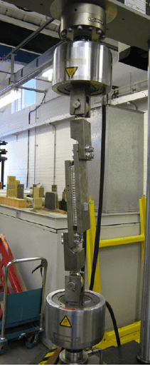
Note: the OP didn't post any pictures of the real-world specimen here so I won't either, but saying that the structure has "geometric imperfections" is understating how irregular and distorted this hexcore was at the end of its manufacturing process.

2. Full model. At first the analysis was done using a "unit" cell, but that raised the suspicions mentioned in this thread, so we modeled the whole core and got rid of analytical "equivalent area" calculations. Still no match.

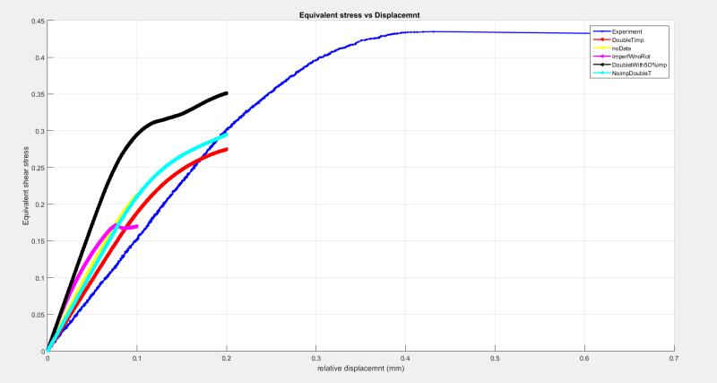
3. Geometric refinement. We implemented things like curved hexagonal cell corners (no change in results) and experimented with single/double wall thickness (there was some miscommunication here). No cigar.


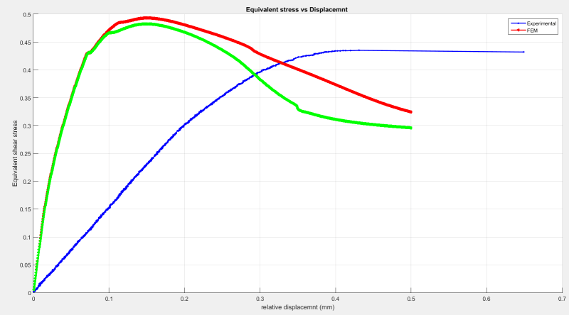
All throughout our investigation I kept bringing up to the OP the possibility that the experimental data was "wrong" (meaning it didn't correspond to what we thought it corresponded to), but this wasn't something I could investigate since I'm a remote collaborator. But now, reading back on the replies to this thread, I believe SWComposites nailed it on his first response, which he reiterated several times: the measured displacements are inaccurate. I think this is very likely the reason for the gross mismatch in linear-elastic stiffness, since we've ruled out many other possibilities (except, perhaps, extreme initial geometric distortion).

I thank everyone who contributed to this thread, you guys have taught me a lot. Cheers!
 
Status
Not open for further replies.
Back
Top