Continue to Site

Eng-Tips is the largest engineering community on the Internet

Intelligent Work Forums for Engineering Professionals

  • Congratulations KootK on being selected by the Eng-Tips community for having the most helpful posts in the forums last week. Way to Go!

Reduce the unbraced length for checking LTB of W column using warping resistance?

Status
Not open for further replies.

Ricyteach

Geotechnical
Sep 28, 2011
27
I am running into a problem checking the LTB on a W column. The column supports a carport with "hurricane wind" in Houston; it is being rotated in one direction by a "tilt beam" at the top. I have attached an illustration.

Basically the W column the designer wants to use seems to be failing in LTB (it's at about 150% capacity) because the unbraced length is so high. I am assuming K=2.1 for this scenario based on Table C-C2.2 of the AISC commentary (I have the 13th edition, black cover).

If we could reduce this unbraced length, it should check fine. Could we do this by simply welding warp-resisting plates to the hollows of the W beam, as shown in the illustration? Would this approach reduce the L[sub]b[/sub] and thus increase the critical moment capacity?
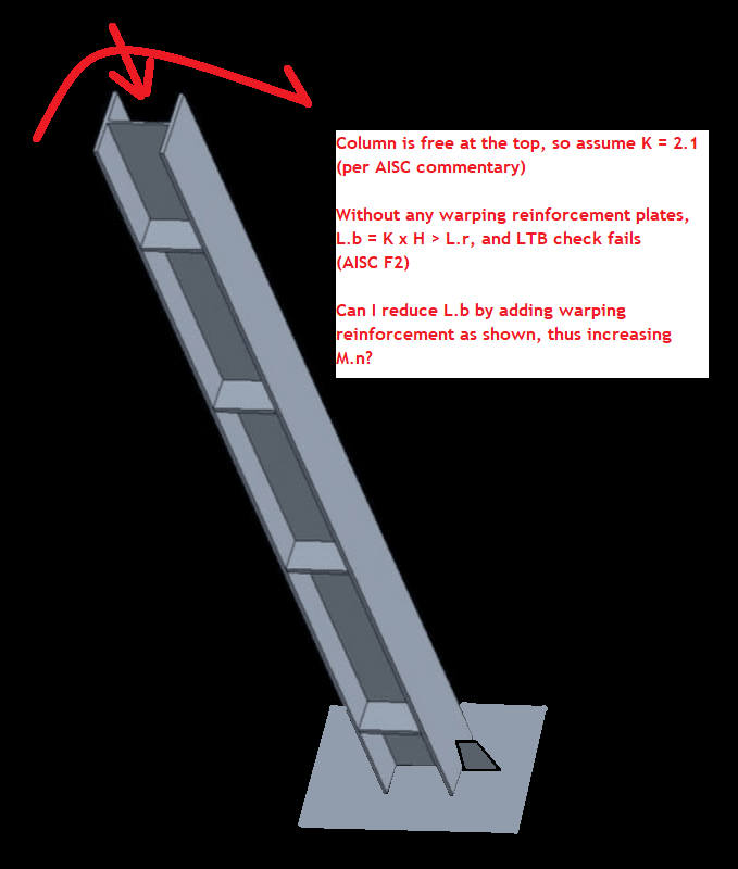
carport_column_illustration_icmeaa.png
 
Replies continue below

Recommended for you

The plates you shown don't restrain the column from LTB or rotation. All they do is change the section properties locally.

In order to reduce Lb you need to provide bracing elements with sufficient strength and stiffness.

 
If you are talking about the stiffeners providing warping/torsion restraint: forget it....they can't do it. I got into this some years ago when I was trying to figure the weld on some stiffeners for a beam with hundreds of ft-kips of torque. The stiffeners saw very little force from this....and didn't restrain warping.

You'll need another strategy.
 
Welp, I guess we'll have to do something else!

Any suggestions other than just selecting a much heavier beam? We can't brace this column; the bracing would get in the way of parking clearance underneath.
 
Can you attach cover plates or maybe another section to build it up?

EDIT: You'd probably want to bolt to the existing since this (appears to be) picking up load on a day to day basis.
 
If it isn't built yet. A heaver Column or an HSS column is probably the most efficient way.

If its in the field you could consider finding ways to increase the torsional stiffness of the section.

Some options
-Add flange plates, channels, or angles.
-'Box' the column with steel plate.
-Add kicker bracing*

*Kicker bracing needs to react on something stiff.

There may be some chance you could do these only over a partial length of the column but that gets trickier.
 
It's still in the design phase so sky is the limit on solutions I suppose.

More detailed view into this sausage factory: the designer is in the process of redesigning this entire thing but there's some kind of government money at stake (it's a solar carport) and the client's customer needs "something" ASAP, before the designer is going to be able to finish the design. So what we're doing is recycling a previous design on this job, and that's probably why I'm finding there is a design problem for this level of wind (the design being recycled was for a significantly reduced amount of wind).

All that to say: since this is just a placeholder design anyway, I am thinking the easiest thing to do is just show some flange plates added up and down the entire column.

But now I have to figure out how to check the column LTB with these plates added. Never had to do that.

...back to the black book.
 
You need to get the section properties of the shape, including the reinforcement and then use AISC Chapter F to calculate its moment capacity for the entire unbraced length.

When I do this I want to ensure that we have full composite behavior between the flange plates and the section.
 
That's a lot easier than I thought it would be.

I suppose I also need to check the local buckling of the flange plates.... do I need to check shear flow of the flange plate welds? Anything else?
 
Well I'm not the designer. But my assumption is a W section- improved or no- is going to be most efficient in this application, since it is overwhelmingly controlled by bending. Just a matter of finding a section that works best.

However HSS might end up winning in the end, since you won't have to do any welding to reinforce the flanges and this might make it more cost effective? But that decision will be up to the designer and the carport vendor; I'm just checking the design (and coming up with a band-aid) at this point.
 
If bending controls and there is no continuous bracing of the compression flange, you would want a HSS section, since it has a superior weak axis flexural stiffness and torsional stiffness and therefore a superior LTB capacity.
 
I looked up the 2005 AISC 360 and it looks like the table you're referencing is the compression capacity effective length modifier. K values for lateral torsional buckling aren't the same as the K values for compression. It's a different buckling mechanism and restraint and length effect it differently. I have to dig out my copy of Guide for Stability Design of Metal Structures to look at the section, but I found a table in my notes and the suggested K value for lateral torsional buckling of a wide flange that is fixed at one end and with flanges unrestrained at the tip is 1.4. I'm assuming from that base plate that you're fixed at the base fully and not restrained with some kind of backspan.

Is it fully free at the top? Something is presumably framed there for the tilt beam and things. Do you get any rotational or lateral stiffness out of that connection to other elements?
 
If you have an analysis software that can do the required stiffness reductions and big/little P-delta analysis, then directly modelling the out-of-plumbness of the column and using the Direct Analysis Method could also be an option, and is quite straightforward for simple cases like this. DAM eliminates the need for the K-factor.
 
Flotsam, that will not deal with bending related lateral torsional buckling, just gross column compression buckling
 
TLHS - yes, I was assuming this was a combined compression and flexure controlled situation given the FBD, in which case the ol' K = 2.1 for flexural buckling may be conservative.

There also is no k factor for LTB in AISC 360. I read through the article you provided, which is quite old and I have to assume there is good reason this methodology has not been adopted.
 
TLHS: yes I am considering it fully free at the top, and yes I am assuming the K factor is the same as for global compression buckling. Perhaps that isn't correct based on your and other comments.

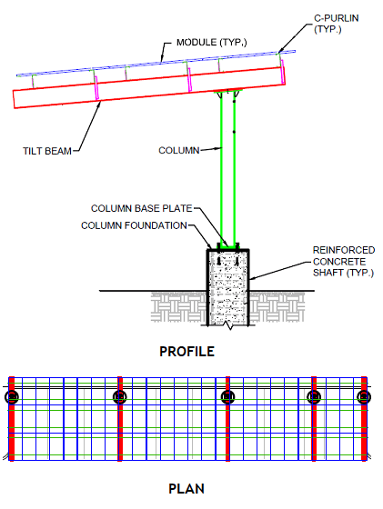
The top probably does have some restraint, but I think it's fair to say it is minimal:

carport_profile_plan_nofckf.png

(EDIT: note that I had posted the wrong plan view for this at one point, apologies.)

The 12" deep C purlins running longitudinally down the carport, with tilt beams running laterally, probably don't restrain the top of that column very much.

As you can probably see: the moment is being applied by the tilt beam which is bolted to a welded end plate at the top of the column. I imagine that during the hurricane, when the bending is applied laterally (in the column strong direction) across the entire carport, the entire structure will tend to want to list to one side or other (in the column weak direction) because of LTB.

Possibly the column top will be somewhat fixed in the weak direction? Possibly the 12" deep C purlins (on 27 ft spans) will prevent the tilt beam cross section from rotating out of vertical, so the carport does not sway the begin to way to one side I am imagining. But I don't think so?

I am assuming each column is seeing bending due to a 27 ft span. In reality only the two center columns have 27 ft of tributary span, so I guess you could argue there is a lot of excess capacity for the pairs of end columns on the righthand side, and single end column on the lefthand side, that isn't being used since their tributary spans are only something like 20 ft for the second from the end column on the RHS, and 7 ft for the two end columns.

My current calculation is that I'm at 150% based on LTB for a 27 ft span. Since I have 5 columns for this carport it means I have enough capacity for 5/1.5 X 27 ft = 90 ft of total carport span. The actual carport span is roughly 87.8 ft... so I think I should probably address this.

So based on all that it seems like K=2.1 is a good assumption... OTOH, I am using Cb = 2.27 (based on the user note of AISC section F1) because I do think the ends are both torsionally braced, and the moments are very very nearly equal and opposite at top and bottom for the controlling load case.
 
You should consider hiring a structural engineer for this. You're missing a grasp of some of the fundamentals based on your first post, and there a lot of other things that can go wrong with a carport detailed like this. Not that there is anything stopping the layout from working, but an experience engineer should review it.
 
Status
Not open for further replies.

Part and Inventory Search

Sponsor