Continue to Site

Eng-Tips is the largest engineering community on the Internet

Intelligent Work Forums for Engineering Professionals

  • Congratulations KootK on being selected by the Eng-Tips community for having the most helpful posts in the forums last week. Way to Go!

Reduce the unbraced length for checking LTB of W column using warping resistance?

Status
Not open for further replies.

Ricyteach

Geotechnical
Sep 28, 2011
27
I am running into a problem checking the LTB on a W column. The column supports a carport with "hurricane wind" in Houston; it is being rotated in one direction by a "tilt beam" at the top. I have attached an illustration.

Basically the W column the designer wants to use seems to be failing in LTB (it's at about 150% capacity) because the unbraced length is so high. I am assuming K=2.1 for this scenario based on Table C-C2.2 of the AISC commentary (I have the 13th edition, black cover).

If we could reduce this unbraced length, it should check fine. Could we do this by simply welding warp-resisting plates to the hollows of the W beam, as shown in the illustration? Would this approach reduce the L[sub]b[/sub] and thus increase the critical moment capacity?
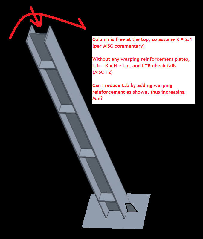
carport_column_illustration_icmeaa.png
 
Replies continue below

Recommended for you

canwesteng: thank you. Yes, it is being designed by an experienced structural engineer (not me). We're just acting as a second set of eyes, asking questions, and we will provide the final stamp of the drawings (as well as the foundation design, which I am much more experienced with). I am not personally stamping the drawings, another more senior engineer in my office is doing that. I have been tasked with looking it over and putting together the first set of calculations. He will review it when I am done. This is a chance for me to learn more about this aspect of structural engineering. Please don't shoot me down with "you're not qualified don't even try" type comments, thanks.
 
Ricytech, there are a number of fundamental items I think need to be clarified. I am not trying to belittle you by any means in saying that, but there are some red flags in your design philosophy that need to be addressed. Apologize if I am incorrect in my interpretation of your messages.

LTB is a flexural failure mechanism, not a compression failure mechanism. You should not be applying K = 2.1 to your LTB check.

If you are transferring moment into the top of your column, you are considering it rigidly fixed at the top. If you are considering it rigidly fixed, but free to translate, then your K = 1.2 for the strong direction. I agree that in the weak direction, you will likely be more in that K = 2.1 due to the lack of rigidity from the C purlins. However, it would seem to me that the column load will be governed in the strong direction based off your floor plan.

Column design is based off of tributary are for your specific application from what I can tell. You shouldn't count on adjacent columns with less tributary area to be helping you. The idea that they will share load makes sense and it will likely be what happens in reality, but that is not following the principles of structural design.

AISC 360-16 has a chapter devoted to Design of Members for Combined Forces, you need to track this down in the black book. This is where you will combine your axial code check and flexural code check (LTB) to see if it meets your design requirements.
 
Thanks for the constructive comments I really do appreciate it. :)

Yes, strong direction bending overwhelmingly controls.

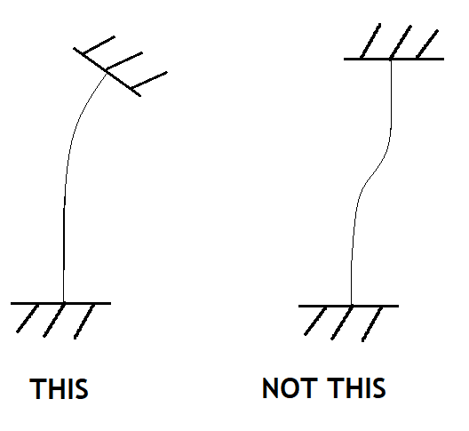
I understand it has to be "fixed" at the top in order to transfer moment, however, even though it is fixed, the plane of the carport roof and tilt beam are fully able to rotate, which means the top of the column cannot maintain a vertical orientation (ie, does not maintain zero curvature with respect to the original column position, even though it does maintain zero curvature with respect to the- rotated- tilt beam):

carport_K_value_kwjtsq.png


To me, that looks a lot more like a "pinned at the top" curvature length of 2.0 (K=2.1) than "fixed at the top" of 1.0 (K=1.2). So that's why I chose K=2.1

But yes I was using a compression-only-mode type of diagram to come up with a conservative K value (I was not sure what other reference to use for the K value). Perhaps this isn't correct and is overly conservative.

I agree with you that using the capacity of the neighboring columns probably isn't the proper thing to do, that's why I was using the "worst-case" single column analysis. Only brought it up for the opinion of others about whether it might be valid to look at all the columns as a system... after all you can't have a LTB mode failure of the type I am imagining (ie, effectively "pinned" at the top and drifting to one side) unless the entire structure drifts to one side together. But again, it was just an idea I was considering; it's probably not the way one wants to do this.

Don't worry, I know to check the combined bending criterion (section H). I am here focusing on LTB because this design is overwhelmingly controlled by bending (the ratio of bending stress to compression stress is about 14.0).
 
OP said:
The top probably does have some restraint, but I think it's fair to say it is minimal:

The columns are bolted to the rafters via a cap plate, and thus have significant rotational restraint against LTB buckling.

This is not a free ended condition as far lateral torsional buckling is concerned.
 
The rafters as detailed don't appear to me to provide enough restraint against rotation. If the end of the beam rolls, it will want to twist the rafter and rack the roof panel. The rafter itself is also poorly supported at the column connections. I would want to provide a clean load path at the column beam interface for rotational loads for both, such as stiffeners that are a continuation of the column flanges, or some fly bracing. Then I would assess as a column with k=2, and L=length of the column. Personally I would conservatively neglect using the C.b for this condition, but I think if both ends have robustly detailed rotational restraint then it would be fine.
 
canwesteng said:
The rafters as detailed don't appear to me to provide enough restraint against rotation.

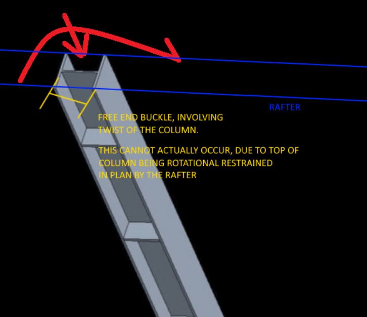
This is the rotational restraint I was referring to. In my opinion this free ended buckling mode cannot occur:

Capture_slnwgc.jpg


The situation is much better than a simple free ended column.
 
@cantwest: yes there is fly bracing from the tilt beam to the purlins as you suggested. The top and bottom of the column are both fully welded to the cap plate and base plate, and both these connections also have a vertical stiffener plate on both flanges of the column. The tilt beam also has a pair of web stiffener plates directly above the bearing area of the column cap plate,

Perhaps these details could mean the top is braced enough to consider k=1.2 like Tomfh is saying.

However I'm still inclined to say it's able to drift out of vertical and is therefore free at that end.

@Tomfh: presumably you'd agree that if there were no purlins- if this was just a column with the tilt beam bolted to the cap plate- and a moment couple was applied by applying a downward load at the end of tilt beam, you'd agree that the column top is free to drift to the left or right, correct? Because nothing would be holding the tilt beam in place.

Now end the thought experiment and put the purlins back in place: What I'm believing is the purlins really don't stop this drifting from happening because the entire carport is going to globally want to drift to the side due to LTB. I suppose if you believe the tilt beam can't rotate both its longitudinal axis also rotate to rack the entire solar array then it wouldn't do this.

However the only thing to prevent the tilt beam from rotating longitudinally and to prevent the column from rotating the entire tilt beam and racking the solar array is the bolted connection of the purlins to the tilt beam top flange (via a welded vertical plate) and the fly bracing. But this isn't being detailed to withstand that amount of twisting and I don't think I would want to count on the purlins and bracing to prevent this from happening...

I understand your diagram though and am digesting it. I see what you mean about the column cross section having to longitudinally twist in order to go into LTB and this is certainly difficult to happen... hmmm.
 
Ricyteach said:
@Tomfh: presumably you'd agree that if there were no purlins- if this was just a column with the tilt beam bolted to the cap plate- and a moment couple was applied by applying a downward load at the end of tilt beam, you'd agree that the column top is free to drift to the left or right, correct? Because nothing would be holding the tilt beam in place.

Yes, if there are no purlins, i.e. if it was a freestanding "T", then I agree the rafter can drift (i.e. the rafter can rotate in plan), and the top of the column can twist. That would be a free ended condition.

Ricyteach said:
because the entire carport is going to globally want to drift to the side due to LTB.

The entire carport can indeed drift laterally, but that is not a lateral TORSIONAL buckle, that is just the carport moving laterally.

Ricyteach said:
But this isn't being detailed to withstand that amount of twisting and I don't think I would want to count on the purlins and bracing to prevent this from happening...

You can check the forces if you're worried. Ordinarily purlins have plenty enough axial capacity. Most roofs rely on the purlins to hold the beams in place and to prevent buckling.
 
I understood what you meant, but I wouldn't count on an unbraced bottom flange of a beam to restrain rotation like that. That being said, it does sound like there is a load path for the twist, just not one shown in the sketch.
 
Status
Not open for further replies.

Part and Inventory Search

Sponsor