Continue to Site

Eng-Tips is the largest engineering community on the Internet

Intelligent Work Forums for Engineering Professionals

  • Congratulations KootK on being selected by the Eng-Tips community for having the most helpful posts in the forums last week. Way to Go!

Reference Point System 1

Status
Not open for further replies.

Auxcron1

Aerospace
Sep 4, 2024
3
Hi everyone,

I would like to ask a question about creating a datum reference system. Me an my colleague were discussing whether the below is an appropriate GD&T notation. There are two 0-point pockets that are used to construct reference point system. It is part of a larger jig. Picture shown below. My question is, is the GD&T notation below correct? The idea is to create 3 planes from two pockets spaced 250mm or further apart. First a datum feature A is constructed by 2 planes. Then datum feature B which is perpendicular and defined as the combined zone of the two planes. And then the third plane which will be the mean plane between the two planes, so theoretically at 125mm. Is this the correct way to show this?

Thank you in advance for your answers.
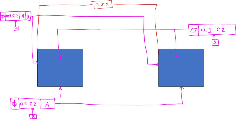
GD_T_t1vus4.jpg


Kind regards,
Kevin
 
Replies continue below

Recommended for you

Greenimi,
"Where CZ is indicated in tolerance indicator all the related individual tolerance zones shall be constrained in location and in orientation amongst themselves"
 
Garland,

This is an excerpt from ISO 5458 5.4.3 Rule C: indication of a single indication pattern specification:

Capture_vzuudi.png


I believe perpendicularity with a CZ modifier could be used to create an internal position constraint on a pattern on holes. I believe the reason you don't see it used that way is because it's not explicitly defined and is confusing.

Ryan.
 
Garland23

Garland23 said:
Greenimi,
"Where CZ is indicated in tolerance indicator all the related individual tolerance zones shall be constrained in location and in orientation amongst themselves

Thank you for the clarification.
I appreciate it.
Now you realize that my statement you quoted is a direct copy and paste from ISO1101-2017, right?
So I am not sure why my replay is incorrect, as you indicated, since I was only copy-paste directly from the standard.

Could you, please clarify a little bit?
 
I asked all this to see if it would be legal per ISO to use perpendicularity with CZ upon a group of features. According to the "letter of the law" in the quote you gave from ISO, it appears that that would be allowed.
But it doesn't sit right with me for perpendicularity to take on the role of location. As Ryan essentially stated, it would at a minimum be confusing.
 
Sometimes there are overlaps in functions. Example, flatness covers much of the same as profile of a surface. CZ says that the zones are lock-stepped to each other, regardless of the underlying control.

I can see that confusion is not realizing that perpendicularity can also control profile. If it was profile, that would seem more familiar, right?

As for me a geometric pattern is a set of identical features or a device/tool used to create a set of identical features. It weirds me out when it is used as a synonym for "group."
 
A very interesting thread. I've seen CZ used is several capacities, but I never thought much about the perpendicularity application.
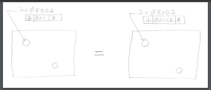
Garland23, does the attached picture sum up your question? (Assume datum feature A is the main face, and TEDs would be given, etc.)


John-Paul Belanger
Certified Sr. GD&T Professional
Geometric Learning Systems
 
 https://files.engineering.com/getfile.aspx?folder=e3949d7f-a165-49d1-8b31-bc878ffcb0bb&file=CZ.pdf
Belanger, yes that's the question I was trying to articulate. Since CZ (in ISO) makes the orientation and location locked among the group, it apparently becomes position in that case. Others can jump in if I'm wrong here.

Still not sure that I like it, but I can live with it :)
 
J-P,

In your attached picture is your intent to compare ASME with ISO?
Or both pictures are intended to be ISO GPS defined parts?
I am asking because simultaneous requirement is not default in ISO hence your left picture (with position, and assuming ISO GPS) since does not have SIM nor CZ means, in my opinion, that their respective tolerance zones are NOT locked to each other (regardless if TED's are present)

I know assuming is always a dangeours thing to do therefore I am asking / questioning your intent.

JP_-_Copy_kmmjze.jpg
 
Garland23,
As previously suggested by Ryan6338, if we follow the logic that the symbol in the first compartment of the tolerance indicator defines external constraints of the tolerance zones (i.e., constraints to datums, if they exist) and CZ defines internal orientation and location constraints between the tolerance zones, then applying perpendicularity with CZ in the scenario shown by J-P could make perfect sense, just like applying flatness with CZ would for nominally coplanar surfaces.

If however, in the given example the pattern of holes was to be additionally controlled for location relative to two perpendicular side faces of the part (let's call them B and C), then I wouldn't personally use perpendicularity symbol in the callout referencing |A|B|C| as perpendicularity is not capable of controlling location to datums.
 
Greenimi, I don't know if that's true about ISO. Perhaps you're thinking about size dims, which don't serve as location (unless the modifier CT is shown).
But to be safe, let's just say I meant the first pic to be ASME style.

Pmarc, yes I purposely left off a secondary and tertiary datum to address Garland23's question more directly.

I sure wouldn't blame anyone for seeing perp with CZ as strange, when position would be the more obvious way of achieving the desired result.

John-Paul Belanger
Certified Sr. GD&T Professional
Geometric Learning Systems
 
J-P,

Belanger said:
Greenimi, I don't know if that's true about ISO.

What exactly is NOT true about ISO? Could you, please, provide more details?
 
I simply said I don't know offhand (without digging up the doc and finding a quote). It was in reference to your saying that "simultaneous requirement is not default in ISO."
Since that's not the immediate topic, I just punted and said that we should assume my first sketch to be ASME.

John-Paul Belanger
Certified Sr. GD&T Professional
Geometric Learning Systems
 
J-P,
I understand. Better safe than sorry.
The original OP question has nothing to do with ASME.
I brought it up (ASME) for my own edification of how to "translate" some concepts (7-33) from .5 to ISO.
By anyway, in ISO the independency principle is defaulted hence I will stick with my statement (which you considered being incorrect).
 
J-P,
If the picture on the left (with position) was per ISO, then the callout would merely control perpendicularity of the holes to A. The spacing between the holes would be left uncontrolled, so in order to turn it on, CZ would have to be added after the tolerance value. It's because the default rule in ISO is that each specified requirement applies independently to the applicable features.

This all would not be a concern if the datum system was A|B|C.

This is one of the differences between ISO and ASME that I call fundamental and which, I believe, allows me to say that the two systems are just seemingly similar.
 
Thank you belanger, pmarc, and greenimi for helping on my question. So essentially, CZ takes any callout and elevates it to a location (and orientation) control. I should have just believed Ryan when that idea first appeared above!
 
This is just nit-picking, but to be precise, CZ elevates any callout to an orientation and location control between the features in the pattern. It is not able to impose external constraints to datums.
 
pmarc,

I think this is where majority of ASME people sturggle (including myself)
pmarc said:
If the picture on the left (with position) was per ISO, then the callout would merely control perpendicularity of the holes to A. The spacing between the holes would be left uncontrolled,

How come, if TED’s are shown on the drawing, the spacing between the holes is STILL left uncontrolled.
The mindset of ISO is of a different approach altogether.
Why we have TED’s then if they are good for nothing?
 
greenimi,
I am not pmarc, but if it's OK to put my two cents in:

Even when the drawing is defined according to ASME standards, basic dimensions are primarily effective when they are utilized by an additional mechanism. This mechanism is datum references or simultaneous requirements.

For example, even if there is a basic dimension from the controlled feature to the datum feature, if that datum feature is not referenced in the relevant geometric tolerance, the basic dimension will do nothing.

Similarly, if the requirement for simultaneity is not applied, the basic dimensions that link the group together will have no meaning. And since the principle of independency applies in ISO, a modifier is required.
 
greenimi,
Burunduk said it well and I would just add one thing to that. In order to make J-P's first drawing compliant to ISO in terms of the completeness of mutual spacing definition between the two features, either:
(1) CZ modifier needs to be added to the existing callout, or
(2) another position requirement with CZ modifier following the tolerance value greater than 0.1 needs to be added and the existing requirement (most likely) changed to perpendicularity.

In either case, the basic dimension will then be for something.
 
Status
Not open for further replies.

Part and Inventory Search

Sponsor