Eng-Tips is the largest engineering community on the Internet

Intelligent Work Forums for Engineering Professionals

  • Congratulations waross on being selected by the Tek-Tips community for having the most helpful posts in the forums last week. Way to Go!

Refinement of tolerance

Status
Not open for further replies.

Siva Mareesan

Mechanical
Apr 30, 2020
10
0
0
IN
Is that a rule in ASME Y14.5 2018 standard stating that the "Geometric tolerance should always be refinement of the size tolerance" which applies to all FORM, ORIENTATION , LOCATION , RUNOUT & PROFILE.
Refined_Geometric_Tolerance_ik0miu.jpg


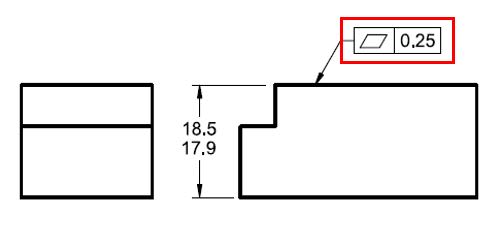
Here in the attachment, The Flatness Geometric tolerance is 0.25 which is less than size tolerance is 0.6. Will this applies to all other symbols too ?
 
Replies continue below

Recommended for you

Siva,

There is no general rule for all geometric tolerances as you implied that "Geometric tolerance should always be refinement of the size tolerance" - in fact there are many cases where geometric tolerances are not refinements of size, or are applied to features and surfaces which are not associated with a +/- directly toleranced size.

There are several situations where the applies tolerance must be less than the size tolerance. Surface flatness, straightness of line elements, circularity*, and cylindricity where rule #1 does not apply. There is also profile where it is a refinement of size (it is very rarely a refinement of size - combination of profile with +/- directly toleranced dimensions is a more complex endeavor than the standard would suggest).

This came up recently, ( might be worth a read.

*This is at least what the standard says, however I think it only truly applies when AVG diameter is specified as it implies an alternate method to evaluate size. Otherwise I think the swept spheres definition of size will prevent circularity error greater than the size tolerance.
 
Siva Mareesan,

Can you show us where the quote is in ASME Y14.5-2018?

Look at your drawing. The toleranced dimension requires that any measurement of the thickness falls between 17.9 to 18.5mm[ ](I presume). Based on Rule[ ]#1, the MMC condition is two perfectly parallel faces 18.5mm[ ]apart. The LMC conditions allows both faces to not be flat.

One feasible and perfectly allowable condition is for the bottom face to be perfectly flat, and for the top face to be 0.6mm out of flat. Your flatness FCF applies an additional control, keeping the top face within 0.25mm. This is a refinement of the original tolerance.

Note how messy and ambiguous the limit tolerance is. This is why you really ought to make it a basic dimension, and add a profile to your FCF.

--
JHG
 
Chez311,

Thanks for your reply.
I understand that refinemet to size tolerance only apply to form. Here you higlighted that profile is rarely used as a refinement to size of tolerance. I couldnt understand one thing, as per my example the flatness of 0.25 can lie any where between the 0.6 size tolerancetolerance ( which means all the points in this surface will lie within a tolerance zone of 0.25 and the tolerance zone can deviate within the size tolerance of 0.6 mm)

Let's assume profile of 1mm is used instead of flatness here , how could a profile of 1mm will lie anywhere within the size tolerance of 0.6 mm. How could all the points in this surface will lie within a tolerance zone of 1 mm and the tolerance zone can deviate within the size tolerance of 0.6 mm?
 
Siva Mareesan,

If you apply a 1mm profile tolerance to the top face, you specify the height as a basic dimension, 18.2mm[ ]perhaps. You would probably use a composite FCF, and the 0.25mm[ ]flatness still would refine the 1mm[ ]profile.

--
JHG
 
Siva,

So what exactly qualifies as a "refinement of size" in my opinion is a little more inexact than it seems. Personally (I know there may be some disagreement) I wouldn't say that the cases I presented (flatness, straightness of line elements, circularity, and cylindricity subject to rule #1) are really strictly refinements of size - its just that a size tolerance combined with rule #1 limits the amount of possible form error and therefore it would be incorrect to specify a form tolerance greater than this. For example in the case in your OP rule #1 (assuming no other notes on the drawing override it) limits the possible flatness error of the top surface to 0.6 - therefore it would not make sense to specify a 0.7 flatness tolerance as it is at best erroneous/redundant and at worse conflicting. Overriding rule #1 (ie: with the Independency symbol) would make a 0.7 flatness tolerance valid as form is no longer limited by rule #1.

The note about "when profile is a refinement of size" is even a bit more abstract - the only case explicitly presented for this would be Y14.5-2018 fig 11-19 (previously Y14.5-2009 fig 8-17, fig 8-18 also showed a similar refinement but was changed to composite profile with all basic dimensions in 2018). Combination of +/- directly toleranced size and profile of a cone is a non-trivial endeavor, search up fig 8-17 and 8-18 for a plethora of discussions on the topic. Suffice to say thats not really a can of worms I want to open.

I know in the thread I referenced Evan noted about Y14.5-2009 fig 8-27 (2018 fig 11-32) however I would personally say it falls somewhat into the above category I mentioned of "not strictly a refinement of size"* because if rule #1 is released it seems to me that a profile tolerance greater than the size tolerance could be valid. This would apply as well to a parallelism tolerance applied to one surface of a FOS. I am interested in other's opinion on this though, as there can be some disagreements when it comes to use of a directly toleranced dimension used for location of a tolerance zone.

*Note that this applies only if the directly toleranced dimension is used both for the size of the feature and location of the tolerance zone of interest as in Y14.5-2018 fig 11-32, if basic dimensions are used to locate the tolerance zone of interest, which is also one side of a directly toleranced FOS then the profile tolerance may be larger than the size tolerance irrespective of rule #1 as it also controls location instead of the directly toleranced dimension as in Y14.5-2018 fig 7-41 (the 0.5 profile tolerance on one side of two 20+/-0.2 widths). This should answer your below question:

how could a profile of 1mm will lie anywhere within the size tolerance of 0.6 mm
 
chez311 said:
I am interested in other's opinion on this though, as there can be some disagreements when it comes to use of a directly toleranced dimension used for location of a tolerance zone.

*Note that this applies only if the directly toleranced dimension is used both for the size of the feature and location of the tolerance zone of interest as in Y14.5-2018 fig 11-32

My opinion is that directly toleranced dimensions do not locate anything. Not features and not tolerance zones. The only exception is when the dimension origin symbol is used, then one can say the dimension and it's tolerance locate a surface relative to a tangent plane at the side of the origin symbol. All other uses of +/- are for size control only. And as noted, for form limits imposed by rule #1.
 
After doing some quick searching you expressed as much in another thread ( While part of it, I did not follow the second half of that thread very closely.

I don't think its uncommon to consider the application of +/- directly toleranced dimensions as providing location constraint, but I see where you're coming from - after thinking about it for a bit I believe this mainly because say we take Y14.5-2018 fig 11-32 if we remove the form control imposed by rule #1 then size by itself doesn't fully provide something which can be construed as a true location control. The limits of size do require that some point on the surface cannot be closer than a minimum of size_LMC away but the maximum is either size_MMC (if subject to rule #1) or size_MMC + the specified form tolerance (if rule #1 is overridden)*.

*Actually I think its slightly more complicated than that, due to rocking/form deviation on the reference surface I think the maximum distance could be slightly greater than this. It would be also affected by whether the applied tolerance controls just form (ie: flatness) or form and orientation (ie: profile with at least one datum feature reference).
 
chez311, regarding fig. 11-32 in the 2018 standard:
The profile of a line requirement provides orientation and form control (form in the sense of the form of line elements akin to straightness). The profile tolerance in that figure doesn't provide a location control because of the lack of a basic dimension. That's why there is no meaning to the location of the profile of a line tolerance zone(s), and therefore the profile tolerance zone doesn't need the size dimension to locate it. Just like straightness, flatness, or parallelism tolerance zone doesn't need to be located by any dimensions. The feature could conform to the profile of a line requirement but fail the size requirement. If we think of the profile tolerance zone as located by the size dimension, the feature would need to fail the profile requirement if it doesn't conform to the size requirement. In reality, the requirements are independent with the only caveat being that the profile tolerance needs to be nonredundant - in the sense of imposing a tighter form control than already provided by rule #1 in conjunction with the size tolerance (and this has nothing to do with location).
 
Status
Not open for further replies.
Back
Top