hydrogen_joe
Mechanical
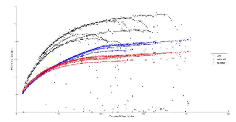
The attached graph plots real data from a h2 refueller that is heavily reduced by a needle valve. The system cascade fills based on the differential between a large store to a smaller vehicle tank. The needle valve gives a system resistance co ‘K’ of approx. 5500 depending on opening.
Data is plotted against theoretical compressible mass flow, assuming both adiabatic and isothermal flows. Due to the high flow rates, it is my belief that adiabatic is more realistic. See formula’s below, both from CRANE TP410, isothermal adjusted as per guidance. I manually choke the flow based on the upstream pressure (which drops during the fill, so difficult to consider it stagnant).
For adiabatic - Could anyone suggest why the higher the pressure differential the more the data deviates from the theoretical prediction, is there an additional adjustment factor? Darcy eq.
For isothermal – the cutoff to choked is more dramatic as expansion factor is not considered, considering Y smooths off the curve but shifts the curve down. Is there another adjustment factor? (1-28)
Lastly, does anyone know of more appropriate ways of tackling this problem?


