Eng-Tips is the largest engineering community on the Internet

Intelligent Work Forums for Engineering Professionals

Regenerative Circuit Query 1

Status
Not open for further replies.

moobe

Electrical
Apr 27, 2010
29
0
0
MD
Hello all,

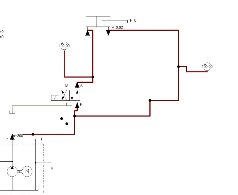
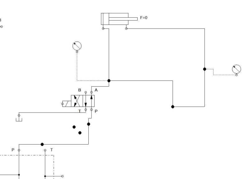
I am trying to play with the hydraulic fluid simulator. I was trying the regenerative circuit to see the increase in cylinder speed during extraction. When I connect the rod end as attach in image1 I get slow speed but I connect as in image2 the cylinder advances real fast. What is the issue? Is there an issue with the simulator. Do both give equal results in real world
image1_outvc7.jpg

image2_bpfo22.jpg
 
Replies continue below

Recommended for you

I concur with hydtools; look at your pressure gauges in your simulation, the pressure on the cap end is lower than the rod end. Can you change the valve to a larger capacity valve and rerun to see how it changes? (I've never used any simulation software so I don't know what capabilities you have in that regard)

Unrelated to your original question, but your second circuit won't be able to retract the cylinder unless there is some external force on the cylinder.
 
The valve must be sized for the sum of the pump flow plus the rod end flow. With a 2:1 cylinder the flow would be twice the pump flow.

Ted
 
The cylinder won't slow down until backpressure is so high that the pressure relief valve or internal leakage bypasses parts of the total flow. Or if the pump rpm decreases due to overload. Or a variable pressure-compensated pump destroke.
The back pressure itself won't slow down the piston.
Regen applications usually fail due to not understanding the flow and pressure intensification effects. Many log splitter builders have experienced that.
Regen applications fit best were gravity provides the force that extends the cylinder piston and the regen flow is used to refill the capped side som the pump flow can be used for other simultaneously used actuators.
 
Thank you guys. I changed to hydraulic resistance of the valve in the software and it work as it should. Thank for your support
 
Sorry but for my understanding. THe more the pressure difference the higher will be flow rate and the speed of the cylinder is only related to flow rate and area of the pistion during extraction. So why the pressure drop does decrease the flow rate of the fluid
 
moobe said:
THe more the pressure difference the higher will be flow rate and the speed of the cylinder is only related to flow rate and area of the pistion during extraction. So why the pressure drop does decrease the flow rate of the fluid
No, it is actually the opposite. The higher speed of the cylinder ie the higher the initial pump flow is the higher the regenerative return flow from the cylinder rod side. And nd the higher flow makes the pump use more power/pressure to overcome the resistance. It is not the pressure drop over the valve itself that decreases the total flow rate to the cylinders capped side. It is that the total pump pressure exceeds the relief valve setting and part of the flow gets lost through the relief valve.
If you look at the entire picture of the simulation you should be able to see that the relief valve setting is 200 bar in the first upper example you showed. You should also be able to set the software to show how high the flows are in different lines of the system. To make that complete you need to set the stroke length, diameters on cylinder bore and piston rod.
 
Status
Not open for further replies.
Back
Top