Eng-Tips is the largest engineering community on the Internet

Intelligent Work Forums for Engineering Professionals

  • Congratulations waross on being selected by the Tek-Tips community for having the most helpful posts in the forums last week. Way to Go!

Regulator failure for a high pressure gas cylinder.

Status
Not open for further replies.

jari001

Chemical
Aug 9, 2013
478
0
0
US
I have to provide 95 psig nitrogen gas to a LN2 dewar switching manifold as the pneumatic actuation gas for the valves that are part of the manifold. The vendor that is supplying this manifold has recommended a high pressure gaseous nitrogen cylinder (size 300) as the nitrogen source since the building doesn't have a nitrogen utility. The cylinder is at 2640 psig when full and a two stage regulator is used to reduce the pressure to 95 psig. I have to follow a standard which requires a relief valve downstream of regulators in the case of the regulator failing open. My question is if the ISA standard equation for determining failure flow rates applies in this situation or does the magnitude of pressure in the cylinder make that equation inaccurate?

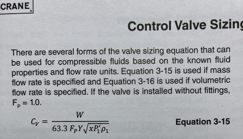
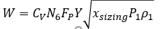
ISA equation I am referencing:
ISA_equation_nrqson.png
 
Replies continue below

Recommended for you

It looks fine to me. The expansion factor, Y, is there and it has the critical pressure ratio built into it.

Crane has essentially the same formula in their compressible flow through control valve section:

47E3C83C-694E-40EC-8B99-15B07AE8D1A9_nbvmqh.jpg


Good Luck,
Latexman
 
Any calculation will be made based on critical flow so volume is fixed, but mass is increased due to inlet pressure.


regulator vendor should be able to give you full open gas flow for pressure relief purposes. It's not like the first time anyone will have asked him...

Remember - More details = better answers
Also: If you get a response it's polite to respond to it.
 
N2 critical pressure is 492 psia. Others can confirm, but I believe the referenced equations are good for compressible flow only if the flow is not supercritical. You didn't state your relieving pressure, but I imagine it is below the Pc.

As an addendum to his question: if the vendor gives a max flow rate based on the regulators failed open, how do you predict the relieving conditions (temp/density)? Normally, with throttling through a regulator I would treat it as an isenthalpic expansion, but does this apply when the fluid is supercritical through the regulator?
 
TiCl4,

I think my choice of words confused you. It's the critical pressure ratio that is important in compressible flow.

Capture_xhrfeh.jpg


Good Luck,
Latexman
 
Latexman,

No, I understood that you meant the critical pressure ratio, past which flow is choked and flow is only increased by increasing upstream vapor density.

However, the N2 is supercritical coming through the two regulators. My first statement was just reminding him of the Pc so that, in the very small chance his relieving pressure for the PSV was above critical point, he may not be able to use the given equation because that applies to compressible gases, not supercritical fluids.

That did bring to mind how he would, following LittleInch's advice about questioning the vendor, handle a vendor stating something like "Max flow through these regulators at 100% open is XXXX lb/hr" -. To properly size the relief valve, he would need to know the upstream conditions (T/P/rho) of the PSV. Since N2 would be supercritical going through the regulators, I was curious if any of the tradition assumptions of modeling the regulators as a throttling process were altered or if a special EOS was needed to calculate the conditions on the outlet of the regulators/inlet of the PSV. I have not messed with supercritical fluids before, so was hoping for some enlightenment on the subject that could also help him with the PSV sizing.
 
My desired relief setpoint is 100 psig.

I got word from the vendor that they recommend treating the regulator as a fully open valve in this case and using the Cv along with an equation to calculate the choked flow through a valve. TiCl4 bring ups a good point I hadn't considered, given that the nitrogen is a supercritical fluid in my relief case. I will see if the vendor has any other feedback once I raise this concern with them.

 
Jari001, I suggest you consider a higher setpoint for the PSV. You stated your header pressure will be 95 psig, which is too close to your desired setpoint of 100 psig for conventional relief valves. Pilot-operated PSVs can handle this operating ratio (Operating Pressure/Set Pressure x100 = 95%), but conventional PSVs will often simmer around an operating ratio of 90%. Is there no room to increase set pressure and use a conventional valve?
 
I understand the issues in a fire or heat imbalance scenario with a supercritical fluid; no heat of vaporization. But in this case, regulator fails wide open, it’s just a flow problem. As long as your PVT method (EOS?) can accurately predict the upstream density of the supercritical fluid, you can use that equation. The ideal gas law may not cut it.

Supercritical fluids are compressible fluids.

I’d love to know what the vendor says about this.

Good Luck,
Latexman
 
The NIST website has isothermal physical property data for nitrogen into the supercritical region, so I would use that data for my calculations if needed.

Since my desired relief setpoint is below the critical pressure, would I take the outlet of the regulator to be at my PSV setpoint to do the flow calculations - this assumes that the initial supercritical flow that lifts the PSV is a transient and that the majority of the relief flow will not be a supercritical flow scenario. Or, would I take the pressure at the outlet port of the regulator to be full cylinder pressure as a conservative assumption and use NIST data or some EOS calculator to get the density of the supercritical fluid upstream of the relief valve?

I'm not so sure what else the vendor can say, but maybe this jogs someone's memory over at the gas supplier and they have some pearls of wisdom to share.

Also, I have to look into whether I can lower the supply pressure of the gas below 95 psig - I now have some conflicting information on what the supply pressure range can be. The datasheet says 95psig to 105psig but the operating manual says 75psig to 100psig. If I can go below 90psig, I can stick to my PSV setpoint of 100 and use a conventional valve with an operating ratio of 0.8.
 
I don't have a MAWP per-se, but I'm taking the 100 psig max delivery pressure from the operating manual as a "do not exceed" value. I could set it at 105 psig if take the datasheet range to be the true range. Since this gas is meant to be valve actuation gas, I didn't think to ask about any MAWP values.
 
Ah, I didn’t know you were bounded on the upper side. Might be good, as you say, to double check.

I would be wary of approaching the lower supply air pressure limit for valves - any additional friction from scaling or worn seats and the valve won’t work properly. I speak from experience here, unfortunately.

Looks like you have a tight range in which a pilot-operated may be your best choice.

Also, I don’t think you will ever be supercritical at the PSV inlet. System pressure will be limited by a properly sized PSV, and pressure will never approach Pc.

Edit: I didn’t know NIST had that data for N2. Neat. However, the regulator should still be an isenthalpic process, so you’ll still need and EoS to predict regulator outlet PVT properties. Or am I missing something there - does the NIST calculator spit out all the properties you need at a given pressure?
 
jari,

I was in one of our plant's files today. They use EL-O-Matic actuators. The actuator spec says up to 120 psi of air. Our air header PSVs are set for 120 psig. The air header pipe spec is a nominal 150 psig spec. The air compressors go on at 80 psig and off at 100 psig. The EL-O-Matic torque tables end at 90 psig. I thought this might help.

Good Luck,
Latexman
 
My gas supplier transfered my questions to the manifold product manager and go the following info:

The changeover manifold has a relief valve built into it for a regulator failure scenario that's set at 120 psig; I wasn't aware of this and it's not explicitly called out in the manual, surprisingly. They state the relief valve was sized to empty one cylinder's worth of gas (300 cu.ft. at 2300 psig) if the flow was straight from the cylinder. The flow curve they gave for that relief valve shows I would have enough capacity at 120 psig with 10% overpressure (112 scfm) if I determine the choked flow rated as if the regulator was a normal valve (63 scfm) or use the ISA equation (91 scfm).

There wasn't any comment about the supercritical nature of the GN2 and how that would affect anything, though I'm not sure they understood what I meant when I spoke about the gas being in the supercritical region of the phase diagram...I sent another email about that topic to see if I hear anything back.

They also confirmed that the supply gas needs to be between 95 psig and 105 psig, and since the PSV is set to 120 psig I can call out the regulator to be at 100 psig with no issue.
 
Status
Not open for further replies.
Back
Top