Eng-Tips is the largest engineering community on the Internet

Intelligent Work Forums for Engineering Professionals

Reinforcement in Precast retaining walls

Status
Not open for further replies.

MHobbs

Structural
Sep 17, 2021
27
0
0
GB
Screenshot_2022-09-06_091752_y0j6uz.png


Hi all,
In my experience the reinforcement detailed in the stem of a retaining wall does not decrease with the distance up the wall.
The moment to be resisted is obviously decreased, i.e the moment about A is greater than the moment about B in the image attached.
Is my experience just very limited or is there a reason why some of the reinforcement is not curtailed part way up the stem?
 
Replies continue below

Recommended for you

In most situations there would be little practical benefit
You will still need some minimum reo for the demand that does exist and for shrinkage, so some steel is needed
Your spacings will be set by what's at the base - here, generally 200mm crs is standard
For constructability you want to set out your top to match so you need crs to align - if not 200mm then maybe 400mm, but 400mm is likely not OK for shrinkage, or is outside of maximum code spacings so you're stuck with 200
It's also confusing for the contractor - if you step down bar sizes (say you need a 16 or 20 at the base but only a 12 up top) - it introduces the risk of errors in bar sizes which will be far more costly than the minimal savings

Most of the cost is in labour, concrete, erection, etc - the actual steel component isn't much of the $$ value
 
Looking at it from a precast industry perspective, if this was a standard product that the precaster sell all of the time, then yes you should remove as much steel as possible. This will bring more profit in the long run. If you are just going to precast a handful of it, then there is no reason to make the cage more complicated.
 
Mhobbs:
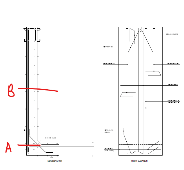
Of course, you don’t want to unduly complicate the labor involved in placing rebars or conc. But, there is nothing wrong with saving rebar stl. where you can without adding much difficulty, or varying the vert. face thickness if that’s easy to do in a casting bed. The vert. back face bars can all be the same size bar, but one being full height and an alternate bar terminating about at your Sec. B height, these two alternate and you fiddle a little to pick a spacing and a bar size. Although, since the two bars are diff. lengths, they could be a diff. size too, to add stl. area per foot of wall, at the same spacing. If the vert. wall tapers from 10" at the top to 14" or 15" at the bot. this reduces the demand on the primary vert. stl. You want the primary vert. stl. to have the max. possible “d” value/distance, so you want the hairpins or “U” bars around the edges of the panels to be small bars and/or inside the vert. stl., maybe the legs of the “U” bars are in the same plane as the primary vert. bars. You don’t want the long/primary vert. stl. to be a “U” bar, talk about a difficult long/heavy/unwieldy bar to bend and handle. The primary vert. bars are “L” shaped with the horiz. leg at the bot. of the ftg. and pointing back into the ftg. Maybe I’m misreading your drawings, those are only of the rebar cage, right? The horiz. and vert. rebars are two mats of stl. held apart by the edge “U” bars. And, you have two mats of stl. in the ftg. too.
 
Thanks for the responses guys, seems like it might be worth looking into especially for taller units where the steel saving could be more substantial.
I'm at a precaster but mostly we do prestsessed beams and slab so our traditional precast elements are quite low volume.
 
Status
Not open for further replies.
Back
Top