kostast88
Structural
- Jul 22, 2013
- 111
I've seen a few different opinions on the matter, so would like to ask the community as well.
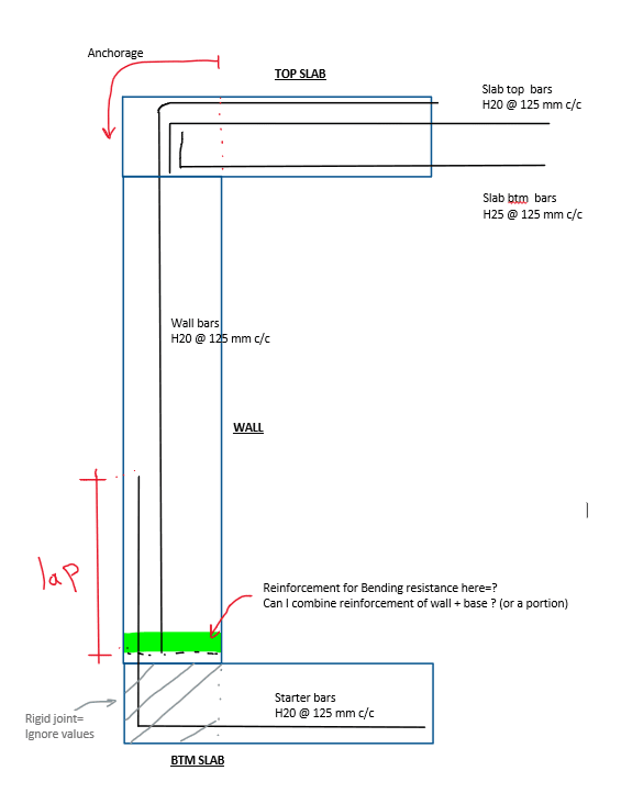
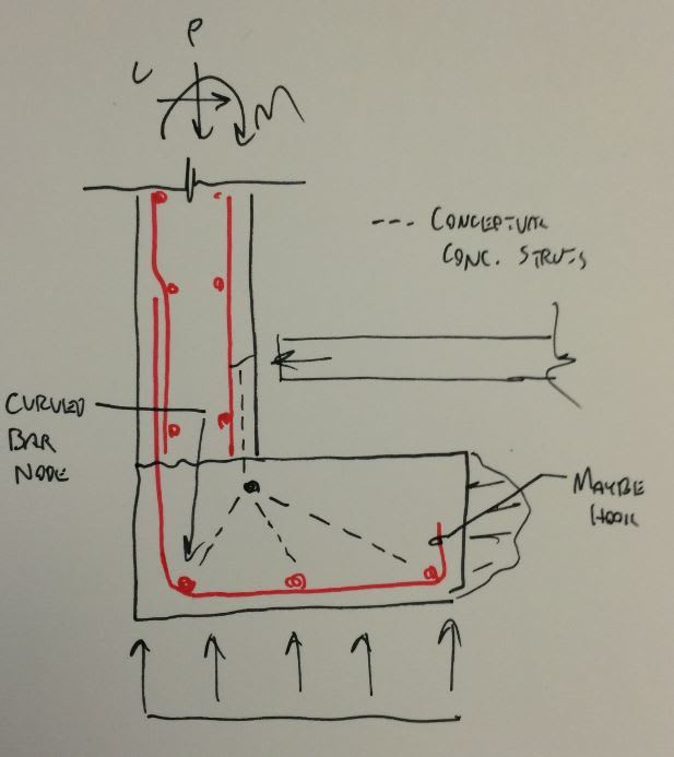
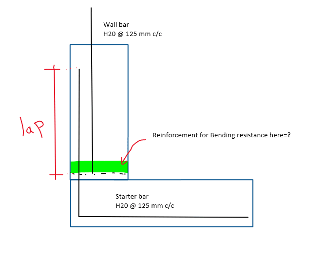
In a RC moment joint, (say culvert wall base) what is the reinforcement for Section Resistance (bending)? Can we add the starter bars to the main wall bars (lapped) to determine the resistance?
If so, what is the detailing condition for that (length required for strength + anchorage length or pure lap length)?