Continue to Site

Eng-Tips is the largest engineering community on the Internet

Intelligent Work Forums for Engineering Professionals

  • Congratulations SSS148 on being selected by the Eng-Tips community for having the most helpful posts in the forums last week. Way to Go!

Reinforcing a PEMB 6

Status
Not open for further replies.

dik

Structural
Apr 13, 2001
26,032
Background
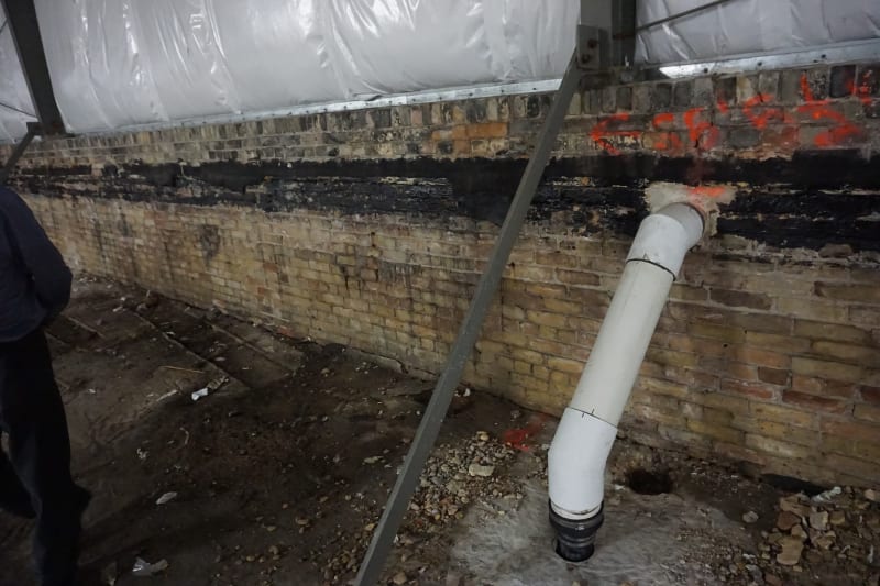
One of my projects is the addition to an existing six storey building. The original building was used for storage, and it’s being re-purposed to Residential. It is a flat slab construction with round columns and capitals and drops. The only sign of distress observed is on the 3rd floor with a narrow, but long, flexural crack at mid span. The crack is nearly half the length of the building. The floor with the crack had almost wall to wall 10’x10’ masonry partitions to create storage compartments. I suspect that this is the cause of the flexural crack observed. The original building is over 100 years old.

A PEMB was added to the top floor (to make it a 6 storey building) several years back. The exterior columns are supported on the original building brick parapet which is about 4’ high and 24” wide. The horizontal thrust is accommodated by diagonal angle struts fastened to the existing roof and the base of the exterior columns. I looked at replacing the struts by reinforcing the structure to behave like a continuous simple steel structure and found the framing members to be a little ‘light’. I calculated the capacity using a design dead load equal to 13psf; the original supplier may have used 10psf; I don’t know, but I expect that sort of design for PEMBs.

Now the Crux
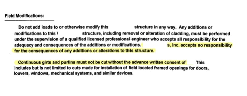
The proposed renovation includes adding new load to the PEMB in the form of added insulation, ceiling and sprinklers. This will likely double the existing dead loading. Because the original design loading is light (or, very tight) I’m considering treating the existing PEMB regular steel building with continuous roof beams and adding BAR material to reinforce it for the moment caused by the added loading without moments at the exterior columns (like a PEMB), without going into a complicated rigid frame design. Can anyone suggest an alternative method or any pitfalls?

So strange to see the singularity approaching while the entire planet is rapidly turning into a hellscape. -John Coates

-Dik
 
Replies continue below

Recommended for you

dik, you know what to do. But pitfalls I'd consider are:
[ul]
[li]Measuring the sections. There's no guarantee they're of the same thickness, floor to ceiling, much less figure the tapers of the beams/columns. Webs are particularly hard to measure. If you measure a dozen purlin thicknesses, how do you know the 13th is the same? Some sections are proprietary. Some measurements are going to have to be made via a lift or ladder.[/li]
[li]How do you tell the owner that not only the building needs to be reinforced for the new loads, but it doesn't work for the current loads and maybe didn't work for the loads in effect when it was designed? So doing nothing is not an (legal) option.[/li]
[/ul]
 
Thanks Jed...
I've already obtained the member sizes... roof beams are all built up and uniform X-section and columns are HSS 3x3 and the end columns are tapered to the haunch. When I first looked at it, it was to see if I could make it non-PEMB and elimnate the diagonal struts from the parapet to the original concrete roof. Based on my original rigid frame analysis it was only marginal (as I've often found PEMBs to be). To eliminate the diagonal struts, would have required reinforcing all the roof beams, so, I didn't bother to check the purlins. That was it. They are planning to add more insulation, sprinklers and a ceiling... doubling the dead load on the structure.

I figured the easiest way to accommodate this was to just look at the added dead load and determine the new moments generated and the BAR reinforcing required to provide that capacity and just beef up the PEMB with the new reinforcing without going into a detailed rigid frame analysis, and neglecting the effect of the rigid connection between the beam and the column on the outside.

I'm not concerned about the main building; the new design loads are likely significantly less than the storage building loads. The city will be approached on this and it may require load testing... I dunno.

I've already advised the owner that the original design is 'marginal'. I don't know what magic goes into PEMB design, but with their fabrication skills and highly developed software they are a tad ahead... I really dislike PEMBs, and think of them as 'throw away' buildings at the end of their life... but, I admire the engineering that goes into them.
[pipe]

So strange to see the singularity approaching while the entire planet is rapidly turning into a hellscape. -John Coates

-Dik
 
Interesting situation.

Your proposed method as I read it is to assume the rigid eaves plastically hinge at the original design load, which caps the horizontal thrust that can get transferred to the base (and therefore avoids increased stress on the parapet/kicker). The additional 3psf or so then is carried by simple-span action between the plastic hinges at the eaves. If you truly have to check the rigid frame, I wouldn't go this route. I'd treat a rigid frame as a rigid frame.

Alternatives:
-Can you or owner obtain the original PEMB load/reaction package (only few years ago, right)? Drawings? I'd expect at least some collateral load in there which ought to cover your assumed 3psf add, or whatever it is. Unless you found it in writing that there is none.
-If the frame is double-pitched, can you run a horizontal tie member like HSS or rod between eave connections. Add verticals if span is too far. Splice it around/through any interior columns. Depending on your actual frame geometry, this may or may not apply. If it does, now you've got a "truss" that can behaves much closer to what you want (and presumably the headroom is fine, given that you're adding ceiling). You do not seem wary of altering (and therefore owning) the struc adequacy of the PEMB rigid frame, although I might have some caution here. This tie would also reduce the horiz thrust from live load, leaving that suspect parapet/brace with much less demand from thrust, a major plus (as you already seem to have identified).
-Is parapet good for wind uplift reaction? Unreinf masonry and all.

Let us know how it goes.
 
Calvin... the original manufacturer of the PEMB is no longer in business and the EOR for it has passed on to wherever engineers go. I'm really wary of altering PEMBs. I'm taking ownership of anything I do. The shop drawings are almost unreadable and there are no design loads stipulated. No existing drawings are available.

My additional design dead load, will be approximately 10 psf.

The existing concrete and masonry (brick) building goes back 100 years. Concrete unknown, but unless highly reinforced or shear issues in normally not a problem. Reinforcing size, type, spacing, and grade is unknown but the change in use likely lessens the loads originally applied.

The moments at the ends caused by rigid frame action reduce the positive moment in the end spans. I would approach this as eliminating the end moment and designing the rigid frame as a 3 span continuous beam (there are two intermediate columns) and forget about frame action. I would just apply the added dead load moment to all beams by means of BAR stock welded to the existing, flat on the bottom, and two rounded bars at the top.

Is there a company that specialises in designing PEMBs, with the exception of the suppliers?

I haven't looked at the parapet for uplift, but the loads are pretty small compared to the masonry mass of the parapet. The brickwork is in excellent condition.

So strange to see the singularity approaching while the entire planet is rapidly turning into a hellscape. -John Coates

-Dik
 
There is an engineer in BC we hire from time to time for Pre-eng design checks, but I am not sure how common they are. I suspect most like Behlen or some of the other Canadian companies have consultants they hire for things that they do not want to do. That is how we found the guy in BC.

A 3D scan of the PEMB will pick up a lot of information very quickly. You would still need to measure some parts with calipers. The old school pre-eng was not nearly as refined at those we see today since they did not have the automation we have now. It might not be that difficult to figure out.
 
Thanks Brad... do you have the name of the consultant in case I need to contact him? It's my experience that usually PEMB manufacturers have their own juju team that can squeeze the last ounce from their system. Most engineers I've encountered have the same experience. I suspect they use loads accurate to 0.1 lb, rather than round them up to 1 lb like I do. [ponder]

So strange to see the singularity approaching while the entire planet is rapidly turning into a hellscape. -John Coates

-Dik
 
Brad... I forgot... I'll check with a couple of PEMB manufactures to see if they have a consultant they use.

So strange to see the singularity approaching while the entire planet is rapidly turning into a hellscape. -John Coates

-Dik
 
dik, at least your PEMB company is out of business, so you have an excuse. And it sounds like you're going in with your eyes open.
We had a case a few years ago where we needed to move a brace in a PEMB. We told the contractor to contract a structural engineer specializing in PEMBs, preferably the original firm. We didn't want our fingerprints on it in any way. And we're not a structural engineering frim, but we do most of our own structural engineering.
Their response:
Screenshot_2022-09-20_163852_ke1uv4.jpg

And this is one of the big PEMB players. This is after they put this note on their drawings.
Screenshot_2022-09-20_164042_dc1eno.jpg


And no engineers that they referenced would work with us (or answer the phone). So we had to do the work ourselves (grumbling all the way), absorbing a few million in liability to make $500.

Do PEMB companies have a shredding machine instead of storage files?
 
Thanks Jed...

You'd think so... I'll try contacting a couple of them tomorrow to see if they have any suggestions. I suspect their market is highly competitive and they do not have the resources to do 'extra' work. Their main 'buck' is made in shipping the box out of their plant. [ponder]

This is one of the reasons that I don't like PEMBs. I've encountered their use, several times, for industrial buildings; these are the last type of buildings I'd use them for. Most owners are unaware of the restrictions that come with them. In addition to advising a client that any alteration may void any warranty they might have, my drawing notes have numerous additional loads that have to be incorporated that can make it easier for an industrial building to use PEMBs. These are from my Project Notes, which I edit for each project:

MBS LOADING

MBS SHALL BE DESIGNED FOR THE FOLLOWING SUPERIMPOSED LOADS IN ADDITION TO THE LOADS STIPULATED ABOVE:

ALL ROOF PURLINS:
DEAD LOAD = 5 PSF UDL
LIVE LOAD = 5 PSF UDL AND TWO POINT LOADS OF 250 LBS AT ANY LOCATION

BUILDING FRAME:
DEAD LOAD = TWO 1000 LBS VERT DOWNWARDS AT ANY LOCATION
LIVE LOAD = TWO 2000 LBS VERT DOWNWARDS AT ANY LOCATION

HAUNCH:
DEAD LOAD = 500 LBS VERT AND/OR HOR AT BOTH HAUNCHES
LIVE LOAD = 1000 LBS VERT AND/OR HOR AT BOTH HAUNCHES

MBS SHALL BE DESIGNED FOR THE FOLLOWING OPENINGS IN ADDITION TO THOSE SHOWN ON THE CONSTRUCTION DOCUMENTS:

MAN DOORS
PROVIDE FOR THE FUTURE ADDITION OF 3' HIGH x 7' WIDE MANDOOR AT ANY LOCATION AT ALL BAYS ON THE SIDEWALLS AND ENDWALLS

OVERHEAD DOORS missed one...
PROVIDE FOR THE FUTURE ADDITION OF 10' HIGH x 16' WIDE OVERHEAD DOOR AT ANY LOCATION AT ALL BAYS ON THE SIDEWALLS AND ENDWALLS

I haven't heard anything negative about my proposed manner of dealing with the added load. It seems reasonable and expedient.

I seem to attract interesting projects... not complaining, I enjoy them... it makes up for the last month of boring projects. [pipe]

So strange to see the singularity approaching while the entire planet is rapidly turning into a hellscape. -John Coates

-Dik
 
I'm sure the PEMB was designed for negative moment at the beam/column connection, so you'll likely have a thicker bottom flange than top flange there. If you're going to assume a plastic hinge forms in the beam at the column face, you do need to make sure that the beam/column connection itself can actually reach that load required. PEMB manufacturers don't develop the capacity of the member for connections, they design it for the load actually present in the beam based on their design criteria. It's possible that some connection components will fail prior to the member, especially if you take into account the likely thin plates and bolt prying.

Also, keep in mind that the built-up shapes are likely only welded on one side. Just something to be aware of and you'll want to run shear flow checks for the web/flange welds.

Source: former PEMB design engineer.

Go Bucks!
 
Thanks for the 'heads up', Staub:
Flanges are both the same. I didn't design it plastically and that may be why the loading was light. I use plastic design all the time and have for 50 years... but only with systems I have a lot of confidence in. If properly designed the entire frame would go 'plastic' at limit load. I checked it for prying and it actually had a little spare capacity. The thin plates increase forces due to prying action to a fair extent. I was a bit surprised. Shear flow was OK. As I noted earlier, I don't like PEMBs, but admire the engineering that goes into them.

So strange to see the singularity approaching while the entire planet is rapidly turning into a hellscape. -John Coates

-Dik
 
dik said:
The moments at the ends caused by rigid frame action reduce the positive moment in the end spans. I would approach this as eliminating the end moment and designing the rigid frame as a 3 span continuous beam (there are two intermediate columns) and forget about frame action.

I took this as utilizing a plastic hinge. I think you still need to consider the frame action though, since the connection is detailed to transmit moment across. If the connection can pass moment, it will pass it to the columns and act as a frame. If the connection can't handle the increased moment, then there's real risk of failure with the lack of redundancy. I think that treating the beam as a 3-span beam for designing the rafter reinforcing is ok, but you still need to run the frame analysis to verify that the connections and columns are ok.

Go Bucks!
 
Thanks again... connections would be checked, and I'll re-run the frame to check, just to make sure; I wasn't planning to, but will.

So strange to see the singularity approaching while the entire planet is rapidly turning into a hellscape. -John Coates

-Dik
 
I don't like the sound of a 4' high brick parapet supporting the frame thrust. How does that work?
 
I wasn't keen about it either, Hokie, but it's been in place for over a decade. The horizontal thrust is resisted by a diagonal anble braced to the existing concrete roof. No signs of distress or cracking, and I looked real close. The load is relatively small and the brick can easily accomodate the load.

Photo Added:

DSC00333_gcln61.jpg


So strange to see the singularity approaching while the entire planet is rapidly turning into a hellscape. -John Coates

-Dik
 
dik said:
Their main 'buck' is made in shipping the box out of their plant.

I used to think that as well until I saw the fees they are getting to actually engineer the PEMB. In my area it's becoming clearer as PEMB's are no longer allowed to be deferred submittals for many jurisdictions, instead having to submit during permitting. One particular project that comes to mind was where they designed a roughly 80k sqft straight forward PEMB and I as the EOR had to design the foundations, stages, loading docks, a connector building between their two buildings at odd angles, and their (PEMB) wall system their fee was more than 3x my fee... and I got beat up by the architect on my fee being "too high". When I saw their fee (more than a dollar a sq-ft) I was, needless to say, pissed and decided I would try to educate architects on PEMB's and the liability we take, thus far it hasn't changed a damn thing.

As for your project, I honestly wouldn't even take on such a project, it screams needing major retrofit, potentially being brought up to code (at least in the US) and seems like a total pain to deal with. I hope you got a great fee for it and wish you the best with the project.
 
dik,

I thought you were proposing to remove the diagonal braces. But don't you have wind uplift to consider as well? The diagonal won't help much with that.

Why not just remove the whole thing, and make the roof structure a rebuild? Probably more economical. All that site welding will cost.
 
Yes it it Hokie. The project owner originally wanted to eliminate the diagonal struts. I went through the numbers and to 'relax' the end column to make it no longer a rigid fram using actual dead loads, I couldn't get it to work without generally reinforcing all the roof beam structure. I didn't look at the CFS roof purlins because it was too onorous to reinforce all. Lateral loading would be undertaken by discreet X-bracing. Support on the parapet was iffy, but calculations showed it was easily capable of taking the vertical loads and it was in excellent condition, being a century old. I was just checking it for existing dead and live loads.

This was the original plan. Just recently, the client will be seeking federal funding, and to do so requires the building insulation, etc. be upgraded. This requires additional insulation, a sprinkler system, and a rated ceiling. The added loading requires that I revisit the PEMB. I was just going to leave it and not modify it. Now, I have to. [pipe]


So strange to see the singularity approaching while the entire planet is rapidly turning into a hellscape. -John Coates

-Dik
 

I didn't realise PEMB fees were so high... I'd always thought they were part of the price. Fees are not an issue at this point... I'm on an hourly rate for this. The project originally started as a small lower floor and main floor addition to an existing six storey building to become a six storey additon. Original walls were masonry, they are now wrinkletin and steel. It's a really neat project, and I'm slowly working my way through it. Any reiforcing of PEMBs I've been involved with tend to be very expensive. That's why I consider them as 'throw away buildings'.

So strange to see the singularity approaching while the entire planet is rapidly turning into a hellscape. -John Coates

-Dik
 
Status
Not open for further replies.

Part and Inventory Search

Sponsor