Eng-Tips is the largest engineering community on the Internet

Intelligent Work Forums for Engineering Professionals

Reinforcing development

Status
Not open for further replies.

JStructsteel

Structural
Aug 22, 2002
1,331
0
36
US
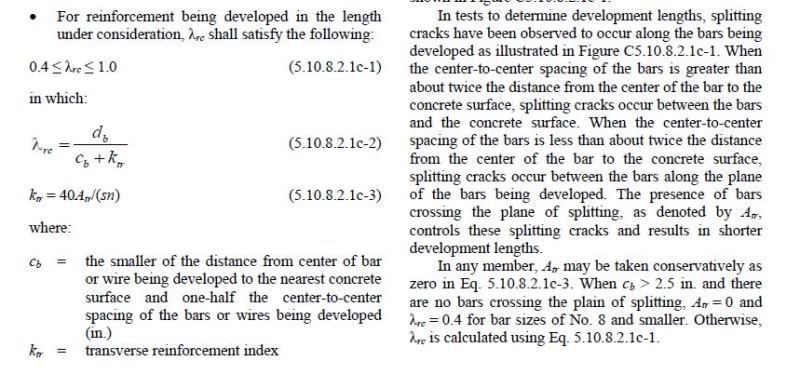
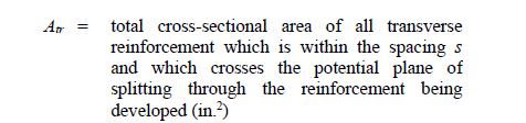
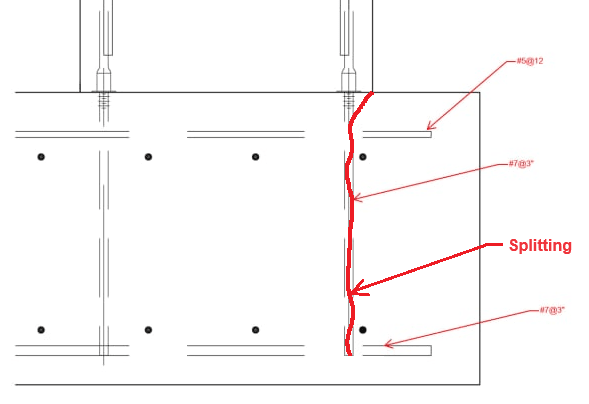
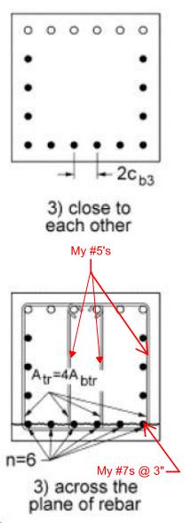
For development lengths of bars that are spaced close together (3"o.c.) what do you consider confinement reinforcement crossing plane of splitting? (ACI 318-14, 25.4.2.3)

I have some #7 bars doweled into a footing. The transverse steel meshes in btween the dowels (top and bottom), and thus steel is crossing the plane of splitting. My edge distance from the dowels to the side of the footing is about 10". Would you consider the transverse bars to be effective to count in the calc? Would you want to see them developed at the edge of the footing?
 
Replies continue below

Recommended for you

If the ACI provisions are the same as the AASHTO provisions we use (which I understood they are), then it shouldn't make any difference whether you count the mesh reinforcement or not. You can assume it as zero and you're still at the minimum for the adjustment factor.

From the AASHTO LRFD 9th Ed.:
lambdarc_iyqhew.jpg
 
Oh yeah, you're right. I don't think you can use the reinforcing mesh, though, if the definition for the area of transverse reinforcement reads the same as AASHTO does.
atr_ijpsej.jpg


If I understand your configuration, there's no transverse reinforcing crossing the plane of splitting, which is between the bars, so Atr = 0, consequently, ktr = 0. I think you're stuck with db / cb.
 
Attached is my section. I have #7 dowels at 3" and the transverse bars cross at top and bottom (wall into a footing)

Do those transverse bars split the plane?
Footing_Development_1_ke4yb1.jpg
 
The potential splitting plane is between the #7 dowel bars, so a plane that runs vertically through the footing, and into the page (2.125" between each bar) in the view you've shown.

Maybe this will help:
ktr_g8rlog.jpg


My understanding would be that Atr = .31 in^2 (I don't think you can count the #7 bars at the bottom), s = 12 in (calculating the adjustment factor on a per foot basis), and n = 4 (you have 4 of the #7 dowel bars every foot)

That would shorten your development length a little (17%).
 
Ok, thanks You would expect the spitting to occur at the top?

For the diagram shown, I dont know where the splitting is occuring? Max V? Max M? ends of the bars?
 
The splitting would potentially occur between the bars over the full the development length. I think it's a stretch to say the the bottom transverse bars are within the development length. You could maybe make the argument that technically they are, since the development length does go all the way to the ends of the #7 dowel bars, but I don't think that's necessarily true in reality, so I would not count them as effective to resist splitting.
 
JStructsteel:
I don't think your #7 dowels would count because they aren't developed beyond the splitting plane, I believe the bars crossing the splitting plane need to be able to develop the splitting tension similar to shear friction bars. so the hooped ties in Bridgesmith image would count but your vertical #7 dowels likely would not count for at least the development of the bottom reinf.
 
I agree with what you stated Celt83, but if I'm understanding correctly, it's the development length of the #7 vertical dowel bars that JStructsteel is attempting to calculate.
 
Any reason you can't use larger bars at wider spacing with hooks?

Btw, is your maximum aggregate size in the concrete small enough to meet the bars spacing requirements? AASHTO requires clear space between bars of 1.5 x the max aggregate size, which would limit the max size 1 3/8".
 
I would expect the splitting plane to be something like this:

Splitting_Plane_rjzxsf.png


I would also ignore the footing bottom bars since they are located at the very end of the wall dowels, so they won't help you much.

"s" is the spacing between your transverse reinforcing (which for a typical beam situation is the spacing between stirrups). In this case, since you only have one bar holding the entire splitting plane together, I would use the entire embedment depth for this. (I don't know your actual dimensions, so I'm going to assume 33" in the calc below.)

As BridgeSmith already said, "n" should be 4 since one of your footing top bars spaced 12" o.c. gets shared among 4 of your wall dowels spaced 3" o.c.

This gives you:
Ktr = 40*Atr/(s*n) = 40*(0.31 in²) / (33in * 4) = 0.094​

This is barely an increase over you cb value of 1.5.

Also, in order to use the transverse reinforcement, the bars would need to be developed on each side of the splitting plane. Since you only have 10" on the exterior side, it doesn't look like you have enough room to fully develop the bars, possibly even if you use hooks. In a typical beam situation, the stirrups wrap around the longitudinal reinforcing, and that is considered to be adequate to prevent splitting, so maybe using U-bars that wrap around the wall dowels and that are fully developed into the interior side of the footing would work in your situation.

Even still, I would have some hesitancy relying on just one plane of transverse reinforcing close to the end to prevent splitting when you typically have multiple stirrups throughout the entire development length.

Structural Engineering Software: Structural Engineering Videos:
 
Now that I looked at it again, and thought about it, I agree with the s being the spacing of the transverse reinforcement vertically in this case, so s = 33". The spacing horizontally is accounted for in the calculation of Atr.

I wondered about the development of the #5 transverse bars beyond the plane of splitting, but I didn't see anything in the AASHTO spec that required that. It would make sense, though, since those bars would resist the potential splitting by tension in the bars.

I do think that the #5 bars, subject to being developed on both sides of the splitting plane, could be considered, since they would work to prevent splitting in the region where they are. The lack of additional bars through the splitting plane is accounted for by Atr and s. However, changing them so they are developed, is probably more trouble than it's worth for the small reduction in development length.
 
I would expect the splitting plane to be bar to bar (perpendicular to the #7) since my bars are so close together.

Im trying to get a #7 developed into my section (30" deep)

I guess its not clear where the splitting plane reinforcement can be? In the picture below, is the "s" dim the spacing of the ties?

Splitting_plane_rrsicv.jpg
 
The splitting plane you are showing in the above post is also correct. Your drawing shows the view looking down, and my drawing shows the view from the side.

"s" is the spacing of the ties. Since we're only considering the top reinforcing to prevent splitting, you only have one "tie", so your "spacing" (in the vertical direction) is the entire embedment depth.
 
I guess its not clear where the splitting plane reinforcement can be? In the picture below, is the "s" dim the spacing of the ties?

Theoretically, the reinforcing that resists splitting can be anywhere within the development length. Practically, bars at the edge of that plane, such as the #7 bottom reinforcing, aren't going to much of anything to prevent the concrete from splitting and allowing the bars to slip.

Yes, s would be the spacing of ties. In your case, s would be the vertical spacing of the horizontal bars that cross the plane that runs between the #7 dowel bars and from the top of the footing to the bottom of the dowels. Since there's only 1 row of transverse bars, the spacing of the transverse bars vertically is somewhat hard to define, but I would say it's either the 33" or infinity (which would make ktr = 0)
 
Thanks ProgreammingPE. I agree with that. My Atr though would be multiplied by the number of bars in my section. I could vary the spacing to help.

Also though, moot point if everyone feels the bars should be developed, even if Atr=area that crosses the potential plane. I get they envision this to be for ties.
 
JStructsteel said:
My Atr though would be multiplied by the number of bars in my section.

In the Ktr calculation I did above, a 12" wide section was being considered so that Atr was the area of one #5 (0.31 in²) since the bars are spaced 12" o.c. This 12" wide section has 4 wall dowels spaced 3" o.c. being developed, so n = 4.

If you are suggesting multiplying Atr by the number of bars in the section, then you are considering a section that is wider than 12". This means you'd have to increase n as well, and you'd end up with the same result.

If you're having issues developing the wall dowels, then you should just add hooks to them.
 
Also though, moot point if everyone feels the bars should be developed, even if Atr=area that crosses the potential plane. I get they envision this to be for ties.

Yes, for the bars crossing the plane to be fully effective to prevent splitting, they would theoretically need to be fully developed on both sides of the plane. Taken to the extreme, if the bars only extended 1" past the plane, how much would they resist the splitting? Not much. Theoretically, you could consider partial development of the #5 bars, and reduce the area accordingly, but the difference would be so small (you have 8" of length, while the full development length for a #5 top bar is 24", so Atr = .103 in^2), I can't imagine it's worth doing.

Again, if the development length is controlling the thickness of the footing, then the typical solution is to put a hook on the dowel bars. Although, if the #7 bars at 3" in the bottom of the footing is for flexural capacity, you should consider using larger bars and/or a thicker footing. We hardly ever go less than 6" spacing in footings or walls.

Another potential problem area is the clearance between the bars at bar laps. With only 3" c-c spacing, at a lap of the #7 vertical (or horizontal) bars, you would end up with only 1.25" clear between bars at the lap. While not specifically prohibited by the spec (AASHTO spec, anyway), it's likely to result in voids in front of those bars, which will have to be grouted after the forms are stripped.
 
ProgreammingPE, I will more than likely use hooks, but since these are dowels, the hooks will have to be 6 different lengths so I can screw them into the female end, thus why a straight dowel would be best. These are precast sections into CIP. I get what you are saying about the s vs n. Per foot or per section you are right, same answer.

 
Status
Not open for further replies.
Back
Top