Continue to Site

Eng-Tips is the largest engineering community on the Internet

Intelligent Work Forums for Engineering Professionals

  • Congratulations SSS148 on being selected by the Eng-Tips community for having the most helpful posts in the forums last week. Way to Go!

Reject on Basic dimension linear measurement 3

Status
Not open for further replies.

S.Sigma

Mechanical
Aug 26, 2020
9
Hi all, first timer here.

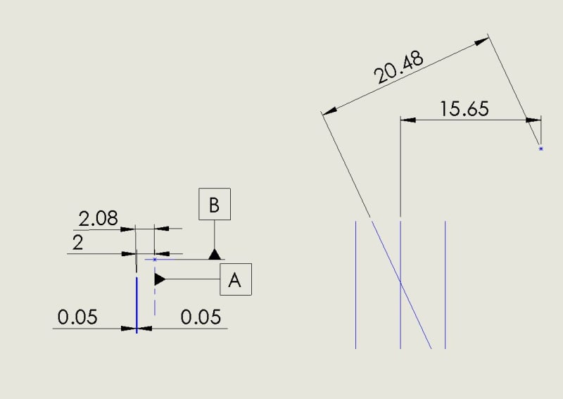
I'm dealing with a customer who wants to reject a part based off the linear measurement of a basic dimension while the surface profile of the feature is within specification.

The feature is a planar surface that is being measured to a point constructed from the intersect of a bore datum and a plane datum.

The surface profile tolerance of the planar surface is .100mm (.004") which, to my understanding, means that the surface may vary anywhere within the +/- .05mm window allowed by the profile tolerance.

The reason that the linear dimension's deviation is higher than .05 while still being within the profile limits is due to the planar surface being at a slight angle, so the distance to the datum point is increased.

In the end, my argument was that if the surface profile reading is within specification, there is no cause for the part to be rejected because, again, to my understanding, basic dimensions have no linear tolerance and are just a location for the window described by the geometric tolerance for the feature to reside.

They want me to provide them with textbook information to describe how basic dimensions have no tolerance and cannot be rejected if the geometric tolerance is within specifications.

Can anyone help with finding this info?

Thanks!

PS - I'm not including a copy of the print for legal reasons.
 
Replies continue below

Recommended for you

Judging by the terminology you are using, I suppose you work per one of the versions of ASME Y14.5.
Maybe some definitions from the 2009 version can help:

"1.3.23 Dimension, Basic
dimension, basic: a theoretically exact dimension."

Also, from para. 1.4, FUNDAMENTAL RULES:

"(a) Each dimension shall have a tolerance, except for those dimensions specifically identified as reference, maximum, minimum, or stock (commercial stock size). The
tolerance may be applied directly to the dimension (or indirectly in the case of basic dimensions), indicated by
a general note, or located in a supplementary block of the drawing format."

One thing I don't quite understand though:
S.Sigma said:
The reason that the linear dimension's deviation is higher than .05 while still being within the profile limits is due to the planar surface being at a slight angle, so the distance to the datum point is increased.

Does the slight angle (relative to what?) result from variation or is it designed that way? In any case, If the tolerance zone is well-defined and sufficiently constrained to the specified datums I don't see how it can be met while there's some distance value from the surface to some datum that does not correspond to the tolerance value in conjunction with the basic dim. numeral.

A simplified sketch to illustrate the problem would probably help.
 
Hi Burunduk,

Here is a quick example, the left shows a zoomed out version of the datum configuration and feature to be controlled. On the right of the image is a blown up example of how the feature sits within the tolerance window and how it affects the linear dimension reading.

All dimensions shown are random and only used for a visual example.

It was not designed to have an angle, the angle is about .3-.7 degrees (exaggerated in the example for clarity) and was just the result of the manufacturing process of this item (which has since been corrected).

Profile_Deviation_Example_gsvjlk.jpg


Hope this helps clarify my position.

In the end, isn't it wrong to reject a basic dimension when its geometric tolerance is within specification?

Thanks again.
 
What specification are you using? ASME or ISO and what version? I know the above assumption is that you're using ASME but you didn't mention it.

The surface profile tolerance of the planar surface is .100mm (.004") which, to my understanding, means that the surface may vary anywhere within the +/- .05mm window allowed by the profile tolerance.

Correct, the feature may vary within that range when properly constrained to the applicable datum features specified in the the profile FCF.

You are correct, basic dimensions do not have any tolerance - they are by definition perfect. They are most often used to define the exact location and orientation of a tolerance zone relative to the specified datum features, and for a profile tolerance they can also be used to define the exact geometry of the feature's size and form.

ASME Y14.5-2009 said:
1.3.23 Dimension, Basic
dimension, basic: a theoretically exact dimension.

It was not designed to have an angle, the angle is about .3-.7 degrees (exaggerated in the example for clarity) and was just the result of the manufacturing process of this item (which has since been corrected).

If the resulting angle is within the specified profile tolerance then it is allowed in the design. Whether or not that was the designer's intent is another matter, but the fact remains that the specification allows it. If additional refinement is desired a tighter orientation tolerance should be added. As you know a paralellism/perpendicularity/angularity tolerance does not actually directly control angular deviation in degrees but limits it within a tolerance zone of the specified width (or diameter - in the case of a cylindrical feature) - some amount of trigonometry is required to determine the actual maximum allowable angular deviation.

In the end, isn't it wrong to reject a basic dimension when its geometric tolerance is within specification?

Yes. What you have measured in your inspection report is not a basic dimension - it is an actual value (of some sort - though not one as defined by Y14.5.1), again your basic dimensions only define the theoretically exact geometry. They define your tolerance zone(s). Additionally the example you showed theres no reason to even compare the 2 dimension to the 2.08 dimension - your basic dimension (2) provides the basic, theoretically exact location when oriented to A and B (assuming your profile tolerance is wrt |A|B| or |B|A|). The measurement reference when measuring the 2.08 value is clearly not measured while oriented to A. Comparison in this manner is faulty.
 
Thanks very much for the reassurance!
Yes, I operate using ASME Y14.5, my apologies for forgetting to specify.
 
S.Sigma,

The GD&T profile tolerance is a tolerance, which the feature must be within. Depending on the geometry, lots of profile tolerances are measurable with calipres or micrometers.

The datums applied on the drawing you are showing look wrong to me. Datums are applied to physical features, only. The datum features must be sufficient to immobilize your part. You probably should have called your customer before fabricating this thing, to clarify what they want.

--
JHG
 
Just for clarification based on drawoh's latest reply - I asssumed the sketch in your (26 Aug 20 20:12) reply was just that, a sketch to show the deviation you were talking about and not representative of the actual drawing. Drawoh is indeed correct, your datum feature symbols A and B should always be applied to actual physical features, hence datum features. If this is not the case on the drawing it is not compliant to the rules in Y14.5 for datum feature specification.
 
The sketch was indeed only intended to show the deviation i was talking about, it is not representative of the actual drawing or its datum features, just an example of how they interact, Datum A is a hole and datum B in this case is a planar surface.
 
S.Sigma said:
The feature is a planar surface that is being measured to a point constructed from the intersect of a bore datum and a plane datum.

From that and from the sketch you attached at 26 Aug 20 20:12, I conclude that the primary datum feature is a planar datum feature, A, and the secondary datum feature is a bore perpendicular to A. The considered feature which was measured is nominally parallel to the primary datum plane. I don't think that the intersection point between the secondary datum axis and the primary datum plane should be the datum used for measurement. Although theoretically a point and a plane have a location relationship, a point can not orient your tolerance zone, and that makes the required distance and the direction of its measurement ambiguous within the DRF if the DRF is defined only by a point. As to datum feature B, I don't think it does anything for this kind of evaluation.

As I see it the problem you described arose because the location evaluation was conducted normal to the considered (profiled) feature, and measured to the intersection point between datums. Instead, the distance should have been measured normal to datum plane A, to points on the profiled feature.
 
Burunduk, In the actual print, the bore is the primary datum feature, the secondary is actually not shown in my example, and the third datum feature is the plane at the top. Using these 3 features for our reference frame and the solid model on a CMM we can measure the surface profile of the features in question.

I'm not sure how to quote on here yet, but, the datum missing in the example is the datum that controls orientation of the feature, i didn't include it because rotating this feature around the A axis does not affect the linear measurement in my example.

The example was supposed to be mostly irrelevant and just a visual aide as to how the linear dimension measured may vary while the surface profile reading shows within specifications.

My biggest question was around rejecting parts based on a basic dimension while its geometric tolerance is still within specifications.

I still require some type of literature that leads us to this conclusion that 1) basic dimensions have no inherent linear tolerance, and 2) that you cannot reject something based off of a linear reading on a basic dimension while its geometric tolerance is within specifications.

Thanks for your time!

 
I still require some type of literature that leads us to this conclusion that 1) basic dimensions have no inherent linear tolerance, and 2) that you cannot reject something based off of a linear reading on a basic dimension while its geometric tolerance is within specifications.

For your (1) I'll expand a bit on the definition I provided previously.

ASME Y14.5-2018 said:
3.26 DIMENSION, BASIC
dimension, basic: a theoretically exact dimension.
NOTE: A basic dimension is indicated by one of the methods shown in Figures 6-11 and 10-1.

3.27 DIMENSION, DIRECTLY TOLERANCED
dimension, directly toleranced: a dimension with an associated plus/minus tolerance or limit dimension values.
NOTE: Where a plus/minus general tolerance is applied to a dimension, the dimension is considered a directly toleranced dimension.

If a dimension is indicated basic it is theoretically exact to the value indicated (either on the print or 3D CAD/math data). If a dimension is associated with a plus/minus or limit tolerance it is no longer basic, it is directly toleranced. The two are mutually exclusive.

For your (2) its a simple extrapolation of the above. A basic dimension has no tolerance, and tolerances are our limits for acceptance, so considered by itself does not provide any requirements for acceptance - unless you want to suggest that you will only accept a theoretically perfect part. These parts do not exist in the real world so that would be a bit absurd wouldn't it?

Only with the addition of a geometric tolerance can we establish limits for acceptance. A part defined with only basic dimensions provides no such limits.
 
S.Sigma,
I think you are focusing on the wrong problem here. Profile is among other things a location control and it does set location limits disposed about the true profile defined by the basic dimension.
Truth is if a planar feature is located to a datum by a basic dimension "A" and a profile tolerance within "x", the distance from any point on the surface to the datum should not be less than A-0.5x or more than A+0.5x.

It's not wrong that the customer uses a linear distance measurement to tell whether or not the feature conforms to the profile tolerance. The problem is that the measurement - if truly represented by your illustration that has the values 15.65 basic versus 20.48 measured (exaggerated for visualization, I know), was done at a wrong measurement direction and to a wrong reference. They shouldn't have measured from the surface to a point. That point is not useful other than being the default datum reference frame origin when it is established at the intersection of datums. Rather, it should have been measured from a theoretical plane, and normal to it, to the profiled surface. The theoretic plane I'm talking about is one of the two established by the primary datum axis and is part of the 3 planes datum reference frame, and the profile tolerance zone should be parallel to it. Per your illustration, instead of measuring in a fixed direction related to the DRF, they measured normal to the actual produced surface that is being controlled, so the measurement direction as shown in your sketch would vary with the orientation of the actual measured surface, from one part to another.

I wouldn't go out of my mind to prove to the customer that a basic dimension has no tolerance, especially in light of the wording of FUNDAMENTAL RULE (a) which I quoted in my first reply in this thread. Instead, I suggest showing the customer how the feature conforms to the tolerance when it's location is evaluated correctly.
 
Chez,
Thanks again for the help, I really appreciate it. I can only hope that these things are enough to convince them.


Burunduk,
I think maybe you're focusing too much on the rough sketch example I drew up for this.

While I believe I understand what you're saying, I don't see why there is a problem with measuring surface profile by using the solid model in a CNC CMM which gives the theoretical exact features already, and using the data derived from points on that surface and the measured datum features to calculate the surface profile reading via the CMM's software.

If the surface profile specification calls for all 3 datum features, how can you quantify a surface profile measurement against just one datum? Don't the other datums further locate/constrain the geometric tolerance limits?

And yes, they measured normal to the actual produced surface which would vary from part to part.

I should specify that I did not mean that basic dimensions do not have a tolerance because I know they're toleranced, but what I guess I'm trying to articulate is that they have no inherent direct linear tolerance of their own and must be controlled by their geometric tolerance limits.

Thanks again for all the feedback!
 
S.Sigma said:
I don't see why there is a problem with measuring surface profile by using the solid model in a CNC CMM which gives the theoretical exact features already, and using the data derived from points on that surface and the measured datum features to calculate the surface profile reading via the CMM's software.

I didn't say there is a problem with using a solid model in a CNC CMM. I pointed out that the measurement has to be done correctly, regardless of the specific inspection equipment/process.

S.Sigma said:
If the surface profile specification calls for all 3 datum features, how can you quantify a surface profile measurement against just one datum? Don't the other datums further locate/constrain the geometric tolerance limits?

Your primary datum is a datum axis that constrains 4 degrees of freedom, including two translational degrees of freedom, one of which is the one that is relevant to the parallel location relationship between the surface in question and the datum axis. The secondary datum reference seems to just orient your tolerance zone in a way that doesn't affect it's basically defined location and the tertiary datum constrains translation parallel to the surface which is, well, simply irrelevant to that surface.

S.Sigma said:
And yes, they measured normal to the actual produced surface which would vary from part to part.

And that's part of the true problem. It's a red flag that indicates that the measurement can't be correct. This is not how a profile tolerance related to a DRF is evaluated.

My advice is - focus on how the correct evaluation should be done. Discussing with the customer the theoretical nuances of how a basic dimension has tolerance in one sense and doesn't have tolerance in another sense is not likely the way to resolve the disagreement.
 
Thank you Burunduk for the clarification, this helps a lot.

All my best,
S
 
S.Sigma,

The problem you are facing just proves how important for the industry is to have a standard on measurement data reporting practices that clarifies, among many other things, that basic dimensions do not represent variable characteristics of an as-produced part.

See the attachment below for some snaphots of Appendix I of a new ASME standard, Y14.45 - Measurement Data Reporting, which draft is currently being under public review. Although not officially released yet, this should give you some ammunition in the discussion with your customer.

 
Pmarc,

Absolutely.
This is great information, I will continue to review the Y14.45 draft.

Thank you very much!

 
S.Sigma,

Maybe I talked enough already you get my point by now, but allow me to add that if you choose the strategy of emphasizing how the distance value represented by the basic dim. is not what profile measures, it will be a tough way.

See below how the GeoTol Pro guide presents the "Measured values" where they discuss profile reporting. I marked it up in the bottom left corner of the document. According to the specific scenario they chose to show, the distance values are indeed not reported. BUT - they are measured. And then converted to "deviations from basic" (notice how they call deviations from true profile) for the report. Perhaps the distance (location) values .5010, .5002, etc. do not always being read by the measurement device, it depends on the specific method and I guess often the "deviation from basic" is what the measurements detect directly. But those basic-dim. based locations are anyway controlled by the tolerance and must not exceed specific limits. If they do, the feature is clearly out of spec (provided the evaluation was done correctly). So you can't tell the customer he shouldn't measure distances.

20200829_003731_crp2no.jpg


Again, my advice is not to attempt to fight the relevance of the basic dim. to the tolerance but to show the correct way of finding the numbers that represent that basic-dim. based locations. Show the customer the specific error in his evaluation and show the correct numbers that are somewhere near the basic dim. just as the customer wants to see.
 
Burunduk,

I agree, I have definitely switched my focus to how surface profile should be measured and reported.

Could you tell me what book this page came from?

Thanks again for all the help!
 
Status
Not open for further replies.

Part and Inventory Search

Sponsor