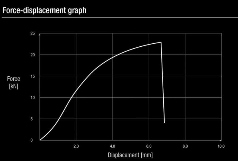
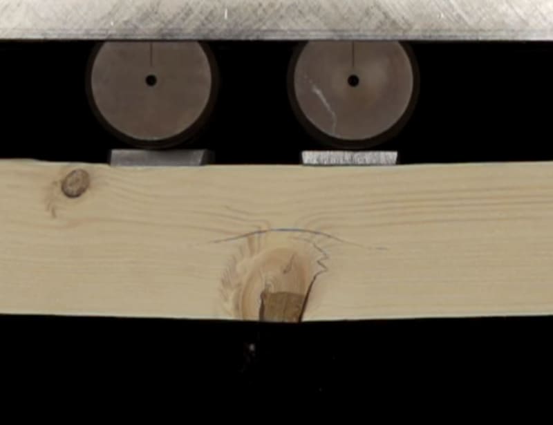
Is it okay to apply the Repetitive Member Factor to a 3-ply wood beam? I have done it in the past based on my reading of the NDS but thought I would inquire here. I have an existing 3-Ply wood beam and since the NDS says 3 or more members in contact or spaced not more than 24", I assume I can use the Cr factor of 1.15. The beam is currently 9% over without the Cr.
Navigation
Install the app
How to install the app on iOS
Follow along with the video below to see how to install our site as a web app on your home screen.
Note: This feature may not be available in some browsers.
More options
Style variation
-
Congratulations TugboatEng on being selected by the Eng-Tips community for having the most helpful posts in the forums last week. Way to Go!
You are using an out of date browser. It may not display this or other websites correctly.
You should upgrade or use an alternative browser.
You should upgrade or use an alternative browser.
Repetitive Member Factor (1.15) applied to 3-Ply Wood Beam? 6
- Thread starter Ron247
- Start date
- Status
- Not open for further replies.
Jayrod12 said:Twice in my tenure, and I'm pretty sure I just got lucky.
I tend to pick up the title over Christmas each year when smarter/better men are spending time with their families.
Code intentions aside, I've always found it odd that load sharing increases are a thing at all in wood construction. In my opinion, load sharing implies redistribution which implies a ductile failure mechanism of the member sharing its load. As far as I know, most wood failure mechanism are pretty brittle. To a vastly milder degree, it's like bolting three layers of glass together to form a beam and slapping a stress increase on that for variability / sharing. In glass, you're not only not taking an increase, your're probably designating a ply sacrificial. Not that I'm suggesting anybody do that for built up 2x10's.
I feel that you get load sharing from the inherent flexibility of wood members. the deflections at failure are quite in comparison to the relative difference in member elevations. But perhaps that's just me justifying the increase for the sake of keeping it.
And considering this increase only applies to the bending resistance of members and not to the more drastic shear failure and/or connection failure, I can get a bit on board with that.
And considering this increase only applies to the bending resistance of members and not to the more drastic shear failure and/or connection failure, I can get a bit on board with that.
TehMightyEngineer
Structural
I suspect it's less about failure modes and more about the inherent variability of wood and the established allowable stresses. To use your glass analogy, it's 3 glass plies where random glass plies have much more strength than anticipated. Also, wood failure in bending is, to some degree, not entirely brittle. Overloaded wood joists tend to deflect heavily, then crack and split, and then redistribute some or all of their load to stronger neighboring joists prior to the whole thing coming down (based on a few roof failures I've investigated).
Ian Riley, PE, SE
Professional Engineer (ME, NH, VT, CT, MA, FL) Structural Engineer (IL, HI)
Ian Riley, PE, SE
Professional Engineer (ME, NH, VT, CT, MA, FL) Structural Engineer (IL, HI)
jayrod12 said:And considering this increase only applies to the bending resistance..
TME said:Also, wood failure in bending is, to some degree, not entirely brittle.
Wood bending failure is really wood tension failure. And I don't believe that wood tension failure is particularly ductile. Ever been involved in bending some wood members for aesthetics? You basically have to steam the crap out wood before bending it or it blows up when bent. This is why.
TME said:To use your glass analogy, it's 3 glass plies where random glass plies have much more strength than anticipated. Also, wood failure in bending is, to some degree, not entirely brittle.
I realize that it's about material variability and that precisely the problem (it is with glass too). If you've got three plies and one is weak, that one breaks and your left with two good plies, not two good plies and one, still functioning crappy ply.
There might be some serviceable logic in claiming that the strongest plies are also the stiffest plies and, therefore, the strongest plies will draw load before that load is seen by the crap plies. A demonstrable relation between stiffness and strength certainly exists but seems a little sketchy when employed this way.
I can see where this is going so I'll repeat: I've no objection to anybody using Cr. This is theoretical musing for sport.
-
1
- #25
- Thread starter
- #28
The failures denoted in those tests have the appearance of a brittle fracture but the intensity of the brittleness does not appear as severe at is would for unreinforced concrete or masonry. I have been around wood members when they literally broke. You do get some warning and then they pretty much shatter. You hear something is going wrong right before they Rice Krispie on you.
What do you think is occurring at about 10 kN where the curvature changes on the graph? I have tried watching the video slow to see if that is where you can start seeing the bearing plates compressing the wood.
What do you think is occurring at about 10 kN where the curvature changes on the graph? I have tried watching the video slow to see if that is where you can start seeing the bearing plates compressing the wood.
Ron247 said:What do you think is occurring at about 10 kN where the curvature changes on the graph
Vastly out of my depth on this but when has that stopped me:
- I think it's all about the tension fibers being... fibrous.
- Initially, you get stiffening as the fibers align themselves for maximum load resistance.
- At 10 kN, the fibers are done straightening and maybe start doing something like necking whereby your effective cross section, and thus stiffness, is reducing.
- Thread starter
- #30
My theory was partly informed by my own, recent medical adventures. I partially tore a rotator cuff back in November. My longtime doctor, knowing what I'm like, drew me a sketch of how things would unfold. With rest, my old man shoulder muscle would knit itself back together. Or at least try. But post knitting, the fibers would be somewhat randomly oriented relative to load. Five degrees off here, fifteen degrees off there. Apparently, with some strategic stretching (load), the fibers would eventually align themselves more efficiently relative to the loading axis. However, if I worked the muscle too hard, too soon, the reduced effective tissue cross section would stretch out and eventually reach a tipping point where you'd have a cascading/unzipping failure. And since I'm too old and non-olympic for anyone with an insurance policy to risk surgery on me, I'd just have to learn to brush my hair with my left hand.
To an extent, all living tissue must exhibit some commonality.
To an extent, all living tissue must exhibit some commonality.
-
1
- #33
TehMightyEngineer
Structural
KootK said:And I don't believe that wood tension failure is particularly ductile.
Reconsidering, you're probably correct. Though in your video link they have a fairly small depth to span ratio. I'd surmise with a more reasonable span of a typical floor beam you would see excessive deflection or perhaps some lateral-torsional mode before ultimate failure. In short, I'd say my position is that you would get greater stiffness out of the stronger members and we're only talking about an assumed 15% overstrength.
I also noted that the video with the defect they had a some cracking prior to failure. This was minimally ductile in my mind.
KootK said:I think it's all about the tension fibers being... fibrous.
I'd agree with your assessment.
Ian Riley, PE, SE
Professional Engineer (ME, NH, VT, CT, MA, FL) Structural Engineer (IL, HI)
TME said:I'd surmise with a more reasonable span of a typical floor beam you would see excessive deflection or perhaps some lateral-torsional mode before ultimate failure.
For the purpose of sussing out Cr, I think that it's a logical error to give any consideration to what may or may not happen along the path to maximum, pre-failure bending capacity. That, because Cr is entirely about what is happening at the particular moment in time that maximum capacity is reached. Cr doesn't care about the path followed to reach that point in time.
Things such as excessive deflection and LTB that might well precede bending failure in a practical structure are great in terms of providing warning to the villagers but, in my opinion, they affect ultimate bending capacity, and therefore the Cr discussion, not at all.
When it comes to showing whether or not a bending failure is brittle, I feel that the videos show the only thing that would be meaningful to show: a bending failure. And the only way to accomplish that would have been to supply proportions that would produce that result.
TehMightyEngineer
Structural
I should clarify my comments on excessive deflection and LTB. I meant that the "weak" ply would have cracking or defects such that it deflects more (excessive deflection) or begins LTB (if not restrained in a multi-ply beam) or some other failure mode due to cracking and reduced section sooner than it's neighbors. Basically providing rational for my argument that the "weak" ply would distribute 15% of it's load to adjacent plys just prior to failure.
Again though, I do ultimately agree with you. Bending failures in wood are sudden and brittle and don't have a nice yield plateau like steel. Thus redistribution in the idealized sense is likely impossible and the 15% Cr factor is probably just as much a "rule of thumb" as a rational argument for material variability.
I suppose one other consideration is that defects and other such things in wood are likely not located strictly at the point of maximum flexural stress. Thus, you could have a ply fail at a defect at the 1/3 span point (for example), split and turn into effectively a notched or tapered section, while still having full depth at the point of maximum stress for the whole multi-ply beam. I believe this would result in a redistribution of stress even with a brittle failure.
Ian Riley, PE, SE
Professional Engineer (ME, NH, VT, CT, MA, FL) Structural Engineer (IL, HI)
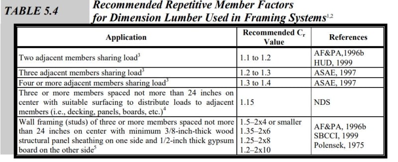
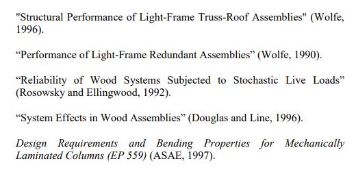
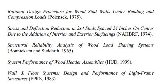
Rooting around online, I found this from a HUD design guide.
- Higher values have been proposed.
- Testing has been performed, particularly on built up headers.
- Some good references there for anyhow who might be feeling super keen. I'd be interested to know the nature of the testing.
- Higher values have been proposed.
- Testing has been performed, particularly on built up headers.
- Some good references there for anyhow who might be feeling super keen. I'd be interested to know the nature of the testing.


- Status
- Not open for further replies.
Similar threads
- Solved
- Replies
- 11
- Views
- 8K
- Replies
- 4
- Views
- 7K
- Replies
- 28
- Views
- 4K
- Question
- Replies
- 12
- Views
- 1K
- Locked
- Question
- Replies
- 5
- Views
- 2K

