Hello,
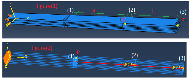
I am trying to replicate the figure (1) loading such that I can apply load at one point figure (2) as I conduct in experiments.
The relationship between the loads are such that :
P2 = P*(a+b)/b and P1 = P*a/b where “a” and “b” are distances as shown in figure (1).
The main goal in trying to do this is that I am able to measure deflection at point Pt(1) where load is applied in figure (2).

The BC’s are such that the left face is prevented from moving in all 3 DOF. I have tried a couple of things which are explained below:
1) Used connectors between Pt 1 – Pt 2 and Pt 2- Pt 3. Note: Pt 1 is not connected to the model, i.e I created a datum point. Pt 2 and Pt 3 are two nodes on the model. I tried using different connector section but was unable to get my model to converge. I tried using “MPC Link” connectors between these points but was unsuccessful, i.e. model doesn’t converge.
2) I created a 3-D deformable wire part which is made of beam element and specified a really high modulus and inertia so they behave rigidly. The wire was connected to the model at Pt 2 and Pt 3 by using “Join connector”. Again was unsuccessful, i.e. model doesn’t converge. I even changed the “Join connectors” at these point to “Tie” constraints. Same issue where model doesn’t converge.
Can someone suggest me how I can overcome this issue and model correctly to apply the right loading as explained above? Any ideas are appreciated.
Thank you
I am trying to replicate the figure (1) loading such that I can apply load at one point figure (2) as I conduct in experiments.
The relationship between the loads are such that :
P2 = P*(a+b)/b and P1 = P*a/b where “a” and “b” are distances as shown in figure (1).
The main goal in trying to do this is that I am able to measure deflection at point Pt(1) where load is applied in figure (2).

The BC’s are such that the left face is prevented from moving in all 3 DOF. I have tried a couple of things which are explained below:
1) Used connectors between Pt 1 – Pt 2 and Pt 2- Pt 3. Note: Pt 1 is not connected to the model, i.e I created a datum point. Pt 2 and Pt 3 are two nodes on the model. I tried using different connector section but was unable to get my model to converge. I tried using “MPC Link” connectors between these points but was unsuccessful, i.e. model doesn’t converge.
2) I created a 3-D deformable wire part which is made of beam element and specified a really high modulus and inertia so they behave rigidly. The wire was connected to the model at Pt 2 and Pt 3 by using “Join connector”. Again was unsuccessful, i.e. model doesn’t converge. I even changed the “Join connectors” at these point to “Tie” constraints. Same issue where model doesn’t converge.
Can someone suggest me how I can overcome this issue and model correctly to apply the right loading as explained above? Any ideas are appreciated.
Thank you
