Eng-Tips is the largest engineering community on the Internet

Intelligent Work Forums for Engineering Professionals

replicating an old circuit- unexpected voltage drop

Status
Not open for further replies.

jabba99

Electrical
Jul 5, 2024
11
0
0
DE
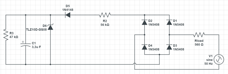
I'm fairly new to circuit design and i stumbled upon this old fashioned circuit everything is fine on the breadboard but i was surprised when i put it on the pcb that whenever i put a resistor parallel to the 10V line ( i need it for the rest of the circuit) the voltage drops to about 4V. I triple checked everything and it's fine. any tips on what could be the issue?

simplified_schem_krfzdn.png
 
Replies continue below

Recommended for you

i used the R3 as an example because i have an IC in parallel to that and R3 is but a feedback loop
I'm using the 10V to power the IC and whenever i solder it on the voltage drops as it does when i solder R3
 
What Lionel said, whatever voltage you see on an open circuit will be divided between the R2 and R3 resistors when R3 is added.
Re-evaluate the value of R2.
Possibly there was a decimal shift in the design calculations.
Should the 56 kOhm resistor have been 5.6 kOhms?


--------------------
Ohm's law
Not just a good idea;
It's the LAW!
 
1) What is the input voltage?
2) Have the components been put onto the breadboard to see that they still function?
3) tlz10d-gs08 doesn't look like a board mount component. See 4) the zener is a small signal device, not a power supply voltage clamp.

What was the original use for this circuit? Where did it come from? Why use it when there are much better circuits available?

Current guess, based on the majority lack of information, the zener diode is damaged.
 
@3DDave
1/the input voltage is 230V
2/ Yes, I tested eveything on a breadboard and it worked perfectly fine which allowed me to test the entirety of the circuit. I started facing issues once i turened to the PCB
3/I know it's a MELF diode and I used it on my breadboard and everything was fine
4/I'm using the zener to have a 10V to supply an IC eventually. upon testing it on the breadboard it works perfectly. However on the pcb the voltage drops and i can't find how

The zener to my bewilderment is fine
 
3DDave said:
1) What is the input voltage?
A question Dave;
Would the bridge rectified have to put out over 20 Volts for a properly spec'ed zener to clamp the voltage across R3 to 10 Volts?

--------------------
Ohm's law
Not just a good idea;
It's the LAW!
 
A lot of work but... build half the circuit on the PCB and the other half in the breadboard. Add/subtract the components to each until you get what you want. That will at least isolate what section of the circuit isn't working as expected on the PCB.
 
If you post a photo of each configuration, particularly one of the unpopulated and populated PCB, that may expose the problem.
 
Thought of another one I've messed up before: Are using a ground plane on the PCB? If so, you don't have AC low connected to DC low, correct?
 
OK, so I went through this earlier 10V/560ohm = 17.9 mA, which is more than 3x the short circuit current available from the 56k resistor.

Since the zener even drops out because all the available current is being sucked up by your load, your output voltage should be in the 3V range

TTFN (ta ta for now)
I can do absolutely anything. I'm an expert! faq731-376 forum1529 Entire Forum list
 
Status
Not open for further replies.
Back
Top