Hi Everyone,
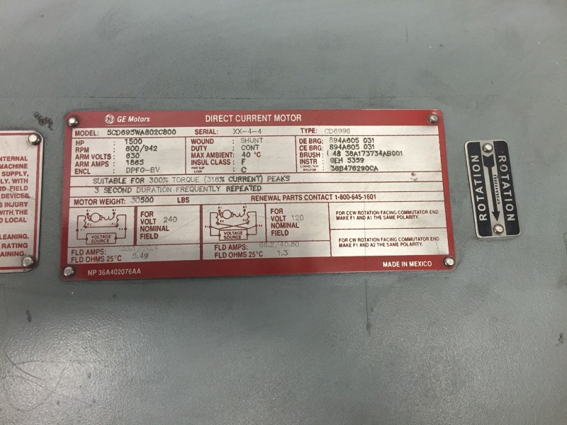
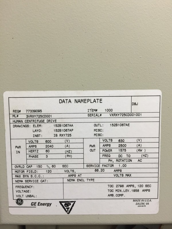
This is my first post here in regards to some motor/drive issues that we experienced yesterday. The motor is a GE #5CD695WA802C800, 1500 HP, 600/942 RPM, 630V ARMATURE, 1865 AMPS, SHUNT WOUND.
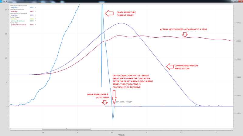
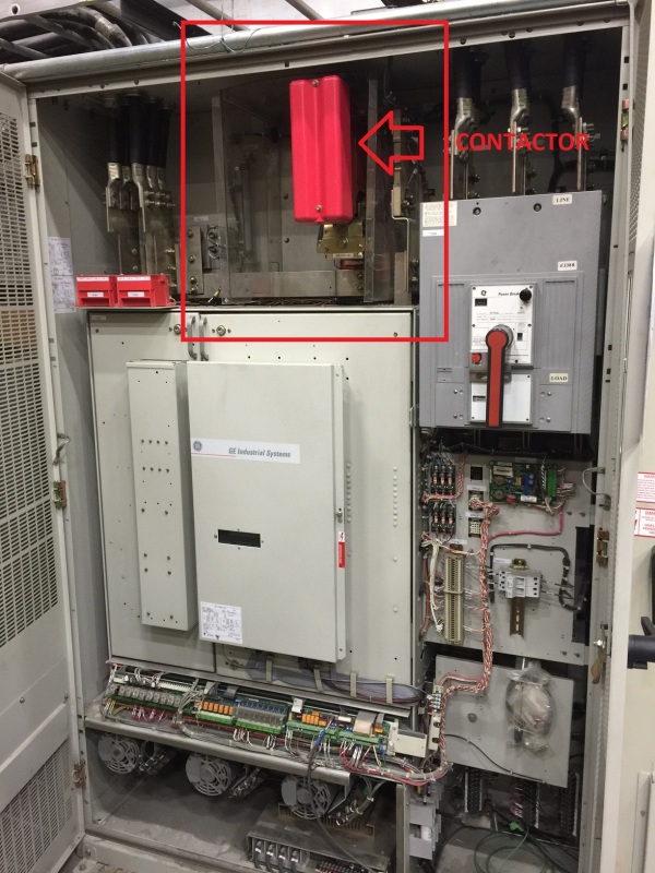
-The first failure we experienced was in the GE drive cabinet, where the drive faulted (assuming self-protection) and the 2400A contactor, which caused a nice loud bang and an arc flash which blew the plastic covers off surrounding the contactor. [This happened as the system/motor was slowing down to a low speed.] We were not able to capture the fault codes from the drive at the time because of someone prematurely disconnecting the drive logic power. Initially, we speculated that maybe the contactor "chattered" causing the arc flash, or simply, the field on the contactor coil has weakened and caused it to behave erratically. I proposed that there may be a hardware issue with the drive itself causing the digital output controlling the contactor to fail, the drive opened the contactor as a means of self-protection, or a few other possibilities. Regardless, they wanted to replace the contactor - so they did.
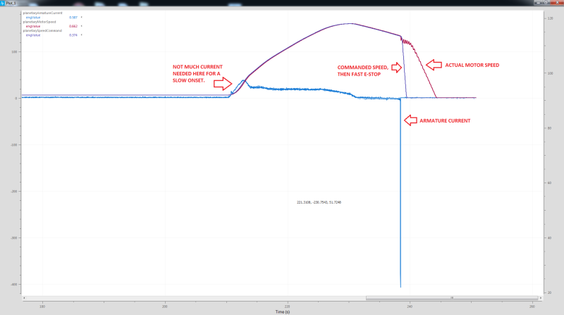
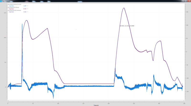
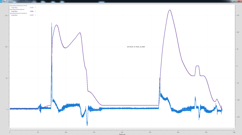
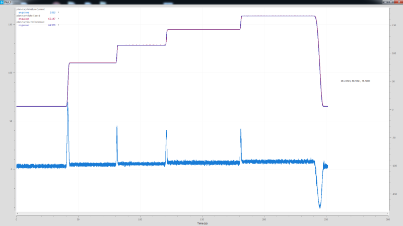
-We were able to retrieve some logs off our computer monitoring system later, indicating that the armature current was abnormally high when the failure occurred. This leads me to believe again, the drive is protecting itself and opening the contactor due to the excessive armature current. We removed the side panels on the motor and the commutator looked ok and the brushes seem to be well within tolerance. There are approximated 297 running hours on the motor. Myself being tired of all the speculating, recommended that we have GE come in for an emergency service, inspect the drive, the motor, and even Megger it, however, this suggestion was ignored, and later that evening a crew decided to continue tinkering with the system.
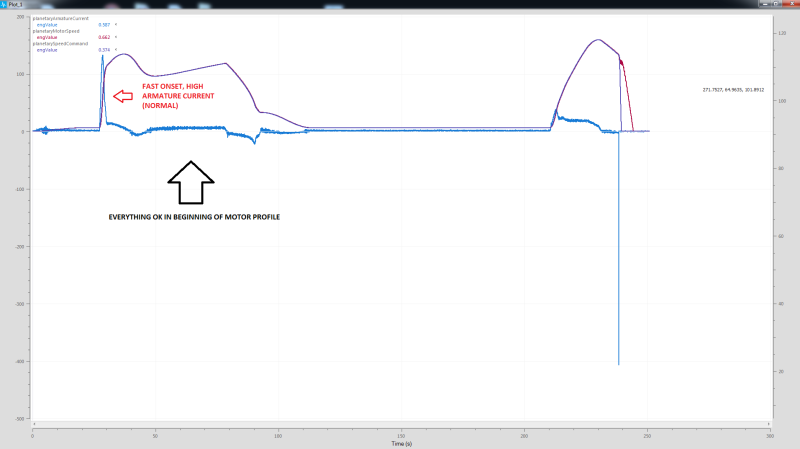
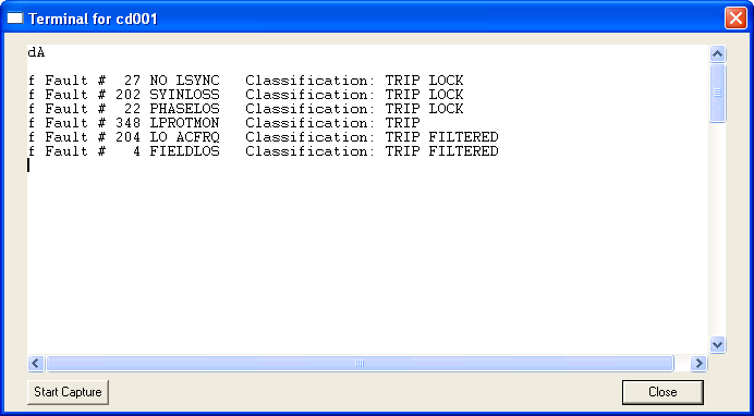
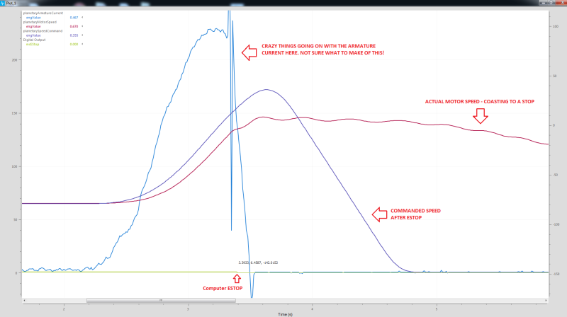
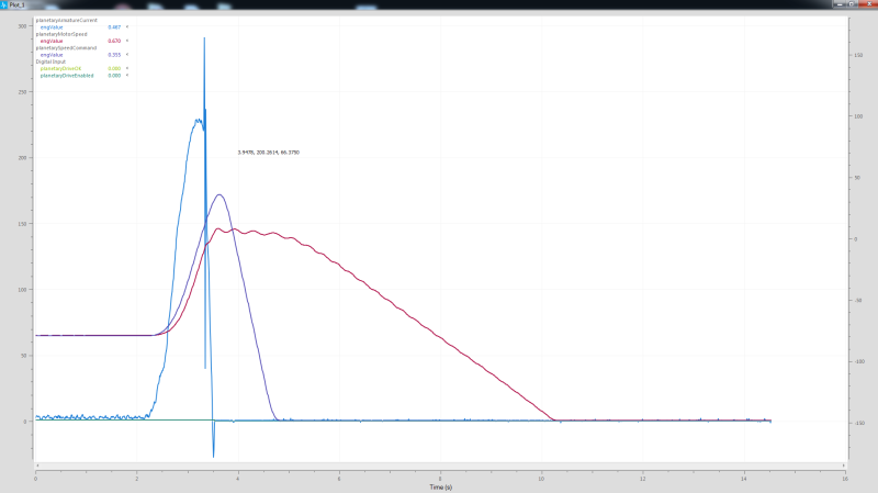
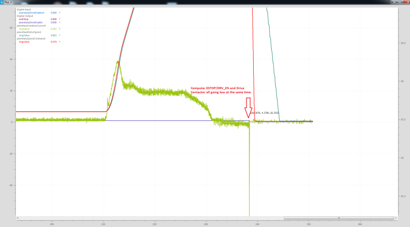
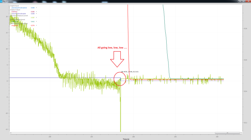
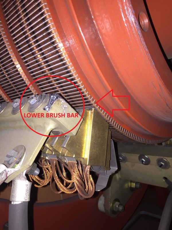
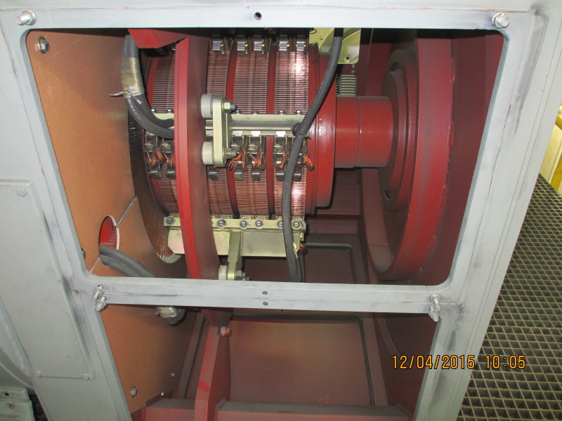
-After they ran the system last night a few times, of course, there was another failure, but not at the contactor. The drive fault code was pretty generic (will follow-up - I don't have it in front of my right now), but whatever happened did some damage to the brush bars in the motor indicating there was a decent arc/flashover last night. See attached picture. [When this failure occurred, it was during onset - increased RPM - acceleration.]
-At this point this morning, I am very upset with how mgmt/engineering has handled this situation, so I blew the whistle, and disabled the device so there is NO chance anyone can start the device, let alone power up the drive.
Now, my questions for this forum are the following:
> In the initial incident, while the motor was slowing down, why would the armature current be so high?
> Is it at all normal for the contactor to violently arc-flash and almost self destruct?
> During the second failure, what would cause such a violent flashover that melted the end of the brush bar?
I am adamant about getting GE in here to evaluate the system, but I personally want to grasp a better understanding of how this systematically failed. Additionally, I am using this incident as a learning tool for myself and to develop some better safety procedures and incident response guidelines.
I sincerely appreciate any information, suggestions, and tips from all in this forum. Please let me know if you have any questions or would like pictures. I have many more pictures I will post somewhere and add the link, since it seems I can only upload one file at time here. Correct me if I am wrong - this is my first time posting here")
Thank you!!!
This is my first post here in regards to some motor/drive issues that we experienced yesterday. The motor is a GE #5CD695WA802C800, 1500 HP, 600/942 RPM, 630V ARMATURE, 1865 AMPS, SHUNT WOUND.
-The first failure we experienced was in the GE drive cabinet, where the drive faulted (assuming self-protection) and the 2400A contactor, which caused a nice loud bang and an arc flash which blew the plastic covers off surrounding the contactor. [This happened as the system/motor was slowing down to a low speed.] We were not able to capture the fault codes from the drive at the time because of someone prematurely disconnecting the drive logic power. Initially, we speculated that maybe the contactor "chattered" causing the arc flash, or simply, the field on the contactor coil has weakened and caused it to behave erratically. I proposed that there may be a hardware issue with the drive itself causing the digital output controlling the contactor to fail, the drive opened the contactor as a means of self-protection, or a few other possibilities. Regardless, they wanted to replace the contactor - so they did.
-We were able to retrieve some logs off our computer monitoring system later, indicating that the armature current was abnormally high when the failure occurred. This leads me to believe again, the drive is protecting itself and opening the contactor due to the excessive armature current. We removed the side panels on the motor and the commutator looked ok and the brushes seem to be well within tolerance. There are approximated 297 running hours on the motor. Myself being tired of all the speculating, recommended that we have GE come in for an emergency service, inspect the drive, the motor, and even Megger it, however, this suggestion was ignored, and later that evening a crew decided to continue tinkering with the system.
-After they ran the system last night a few times, of course, there was another failure, but not at the contactor. The drive fault code was pretty generic (will follow-up - I don't have it in front of my right now), but whatever happened did some damage to the brush bars in the motor indicating there was a decent arc/flashover last night. See attached picture. [When this failure occurred, it was during onset - increased RPM - acceleration.]
-At this point this morning, I am very upset with how mgmt/engineering has handled this situation, so I blew the whistle, and disabled the device so there is NO chance anyone can start the device, let alone power up the drive.
Now, my questions for this forum are the following:
> In the initial incident, while the motor was slowing down, why would the armature current be so high?
> Is it at all normal for the contactor to violently arc-flash and almost self destruct?
> During the second failure, what would cause such a violent flashover that melted the end of the brush bar?
I am adamant about getting GE in here to evaluate the system, but I personally want to grasp a better understanding of how this systematically failed. Additionally, I am using this incident as a learning tool for myself and to develop some better safety procedures and incident response guidelines.
I sincerely appreciate any information, suggestions, and tips from all in this forum. Please let me know if you have any questions or would like pictures. I have many more pictures I will post somewhere and add the link, since it seems I can only upload one file at time here. Correct me if I am wrong - this is my first time posting here
Thank you!!!

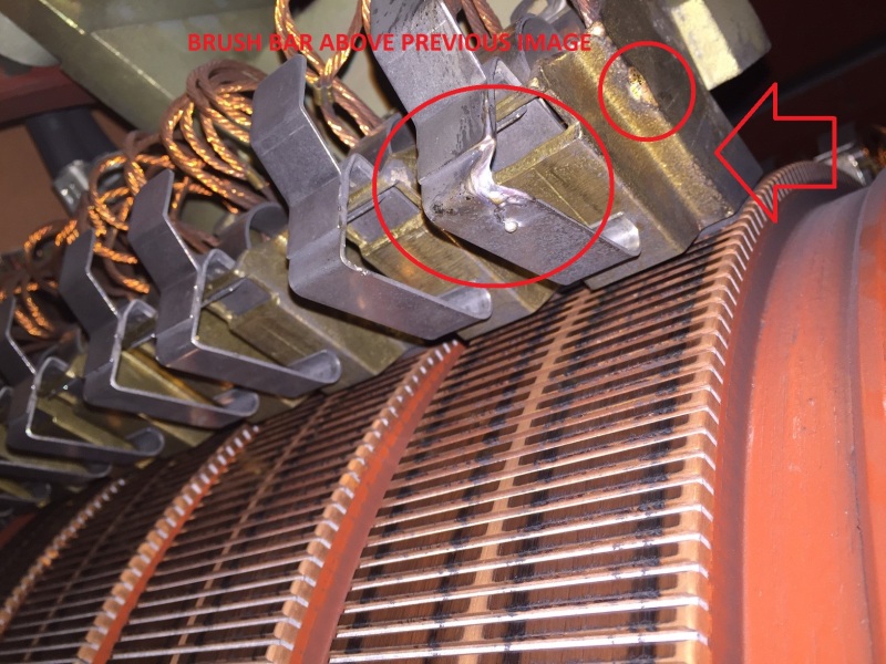
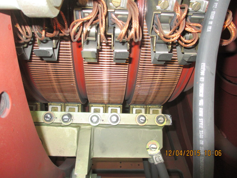
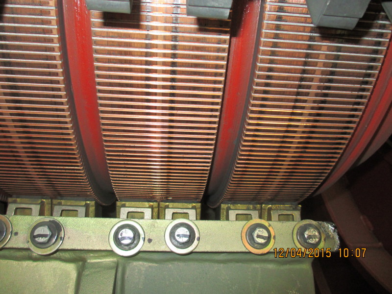
 This picture is zoomed/cropped to show detail)