Continue to Site

Eng-Tips is the largest engineering community on the Internet

Intelligent Work Forums for Engineering Professionals

  • Congratulations KootK on being selected by the Eng-Tips community for having the most helpful posts in the forums last week. Way to Go!

Requesting Some Help with Design of Highly Irregular Flat Slab 3

Status
Not open for further replies.

HiggsBoston

Structural
Oct 3, 2021
5
Hi to anyone reading this,


I am at a complete loss as I attempt to design a suspended flat slab of irregular shape with openings - attached as below. I plan to do some manual calculations before I perform an FEA analysis but I don't know where to even begin since I am a recent graduate and have never laid my hands on anything like this before. It was my understanding that perhaps dividing it into design strips should help the case but it seems that many people on this forum - more experienced than myself - seem to have a disdain for the said method in such instances. I welcome any suggestions or pointers that may usher me out of my situation. I would also like to know of any books or references that I could peruse to equip myself with the required knowledge.

I should note that the client is opposed to the idea of having any beams anywhere or using post-tensioning.

Thanks heaps!
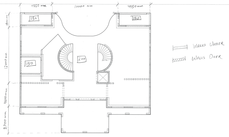
sLAB_onwshe.png
 
Replies continue below

Recommended for you

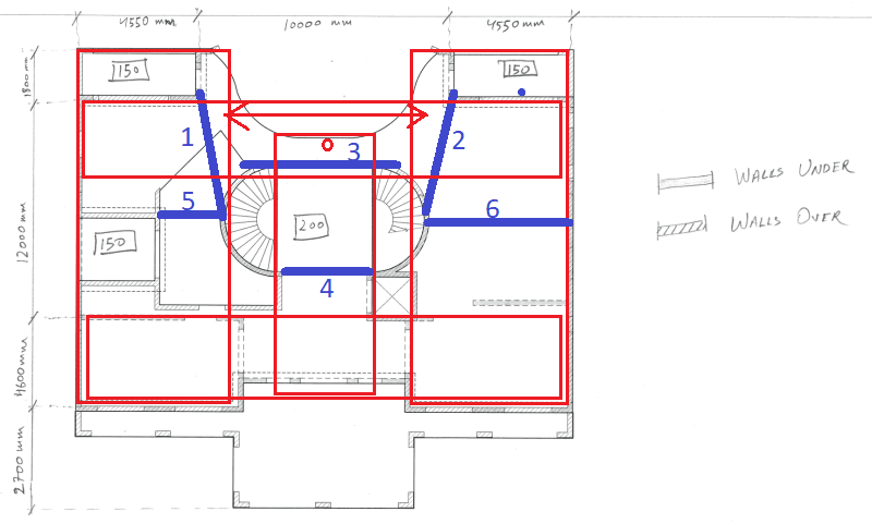
For the manual calcs I would approach it as in sketch. Design in-slab beams (blue lines 1 to 4). Beams 1 to 3 important ones.
Then design simple panels (red) but not modelling the blue beams as support (except beams 5 & 6) with and without to check sensitivity.
When checking deflections, manually, remember to take the accumulative deflections.

A few pointers to a recent grad:
1. The stepped soffits to balconies - try not to take the soffit step to the external wall skin (if that's possible in yr location), stepped v-joints look messy on elevation.
2. On your FE model, check that the deflections at the red circle are not excessive (elastic multiplied by around 4 for LT deflections). Facades sensitive to this differential movement.
3. The 50mm weather step at balconies is very little, strongly consider increasing so that waterproofing and thresholds can be dealt with properly.
4. Adding 50mm to a 200 slab will cost peanuts when compared to what is spent on finishes. Don't be bullied, serviceability on high-end residential is important for you and the client.
5. It's sometimes more desirable to have a level soffit throughout and have a thicker slab to accommodate services and a flat underside. For example, 250 slab and 150 balconies with 100 weather step.

Slab_nyhju0.png
 
If that 'house shaped object and the semi-circular object on the left is an opening, you have some interesting framing issues, unless I'm missing something. Likely beyond a recent graduate. I've not noticed a distain for FEM in these fora... it's a great tool when used properly. w-streng has outline a prelim framing approach... just be careful about the left support of Beam 3... that 'air gap' can be tricky.

Rather than think climate change and the corona virus as science, think of it as the wrath of God. Feel any better?

-Dik
 
w-streng,

I found your suggestions very helpful and they are a big help. I want to add 50mm to the slabs as you suggested but that seems unlikely to happen as the client was restricted by the council policies to build any taller so the client deemed it appropriate to have a total of four stories crammed into ~11.5m height available to them. As it stands currently, I am looking at a floor-to-floor height of only 3m.
With the in-slab beams 1 & 2, can I straighten these out for load computation? And with the semi-circiular stair core, am I supposed to ignore the support available there to simplify the load calculations?

Also, are you able to share some references/examples relating to the design of in-slab beams - as I have limited experience with these yet?

Regards
HB.
 
Dik,

Could you please elaborate on what framing means? Also, that house-shaped polygon was initially proposed to be another setdown due to that being a wet area but that is not the case anymore so it is now just a 200 thick slab.

Regards
HB.
 
w-streng said:
Design in-slab beams (blue lines 1 to 4).
If by in-slab beams you mean 'beams with same thickness as that of a slab', I believe such beams can't be used as load transfer beams.
Can you share a design reference for such type of beams?
As per my understanding, they won't have much stiffness to be considered as supports.
Am I wrong?
 
I agree with wstreng’s framing layout above, although this still needs to be done in FE to get the level of efficiency needed. I can tell you now though that slab is too thin at 200mm.
 
Could I ask what is the significance of blue beams in the design if they are not exactly transferring the loads?
 
HiggsBoston said:
Could I ask what is the significance of blue beams in the design if they are not exactly transferring the loads?
Exactly the question I have raised.
 
Status
Not open for further replies.

Part and Inventory Search

Sponsor