Eng-Tips is the largest engineering community on the Internet

Intelligent Work Forums for Engineering Professionals

  • Congratulations waross on being selected by the Tek-Tips community for having the most helpful posts in the forums last week. Way to Go!

Required airflow and the fan & filter combination for the starter cells in MCC.

Status
Not open for further replies.

Waqas932

Electrical
Nov 9, 2022
5
0
0
AU
Hello everyone,

I am designing MCC. I need to calculate air flow and the fan & filter combination to achieve this for the starter cells.

For information.

• Attached excel sheet gives part numbers for soft starters and contactors
• This MCC is in an A/C controlled room.
• The external ambient temperature is 40ºC.
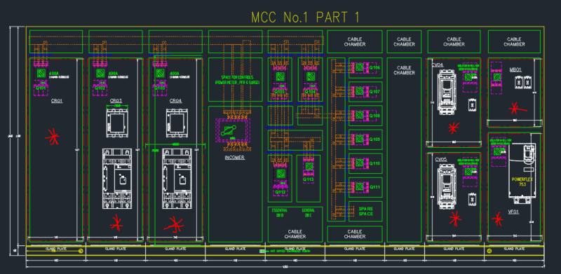
• Cell with CR01 will most likely have an auto transformer in it so we can add the watts lost at a later stage for that one.

The cells that need this cooling requirement are the following with the * symbol.

MCC_f5beeo.png


Could someone please guide me how can I calculate it?

Your help will be much appreciated.

Thanks
 
Replies continue below

Recommended for you

Hi, thanks for your reply.

I did research on it. The thing that I am not able to understand is, how to calculate heat dissipation and internal temperature.

For example, in the CR01 section, we currently have only 1 400Amp mccb( LV432693 OR C40N32D400), with Full load current = 309.5.

How can I calculate heat dissipation for this?
 
Usually the air condition provider have software application for each device at enclosure.
As both mccb are Circuit Breaker , it almost do not dissipate heat, except from the electronic circuit , if they have, that shall be a small heat amount.
You can ask to the 1 400Amp mccb( LV432693 OR C40N32D400) vendor for it.


For the space in question, at equilibrium, heat gain = heat loss.
Heat gain is from outside air temp + solar heat gain + internal heat gain.
Heat loss = heat conducted through walls and roof (assuming internal temp. is > outside temp)
Set up your equation with internal temp. as the unknown. Simple algebra.
 
Normally electrical rooms are designed for a certain temperature and 104 F is usually the maximum allowable temperature exterior to electrical equipment before there are issues. Normally overall heat input of electrical equipment is used to size a AC unit to maintain the internal temperature of an electical room without looking at the temperature inside of the electrical enclosure. Perhaps there may be instances where certain electrical equipment may need to be internally cooled independently but rarely and if so equipment manufacturer will advise requirements and likely provide built in fans etc.

Heat loads for electrical equipment are usually provided by the manufacturer of the electical equipment devices or if not there are industry recommendation guidelines that provide estimated loads for an specific electric device.
 
Thanks everyone for guidance, so now I have power loss, but looking for Max internal temperature of enclosure.


External ambient temperature is 40 degrees
Power dissipation of electrical component (Circuit breaker) is 57.6 watts
Dimensions of the enclosure (1827mm, 560mm, 600mm)

Can someone please guide me if there is an equation to calculate max internal temperature inside the enclosure, or how can we do that?

Best Regards,
 
as you state at OP

This MCC is in an A/C controlled room.

so it shall be about 25 C degree .

So the 57.6 watts will be dissipated by the enclosure steel walls with almost no temperature increase.


The 40 degree is the external ambient temperature outside the building , the A/C will take charge controlling the INTERNAL ambient temperature.

 
I mispoke on my original response. 104F is maximum allowable external temperture of electrical equipment in general. Electric rooms are kept at a lower temperature depending on client preferences and as required to maintain temperature inside of enclosures where electrical devices are located at 104F max. We used 95F as max. design temp of electrical room but I have designed one room as low as 72F per client request. I think the max. temperature of 95F for electrical room will maintain temperatures inside of electrical enclosures at 104F max. as this was our company standard for electrical rooms maximum design temperatures using HVAC systems and we never were required to look at the temperatures that can be developed inside an enclosure if outside of enclosure was kept a 95F maximum.

The actual temperature inside the enclosure can be determind simplistically by a straight heat transfer equation
Q = h(A)(dT)

Q is internal heat dissipation of electrical components in cabinet
A = surface area of cabinet
h = overall heat transfer coeficient (inside air film + metal panel + outside air film)
dT = resulting temperature difference at Q

 
Searching just this site for "enclosure cooling" turns up the following two threads (among many others) that do a great job of explaining why this seemingly simple task is in reality not at all trivial.

thread391-489365

thread248-340558

 
Status
Not open for further replies.
Back
Top