Eng-Tips is the largest engineering community on the Internet

Intelligent Work Forums for Engineering Professionals

  • Congratulations waross on being selected by the Tek-Tips community for having the most helpful posts in the forums last week. Way to Go!

Required area for drop pressure

Status
Not open for further replies.

TBarata

Mechanical
Jul 31, 2019
7
0
0
BR
Good morning.

I need to create a device (or valve) to reduce de pressure in the exhaust pipe of a compressor, from pressures between 1,1 and 10 bara to atmospheric pressure, so I need to create a range of drop pressure in some device that I could ajust the area.
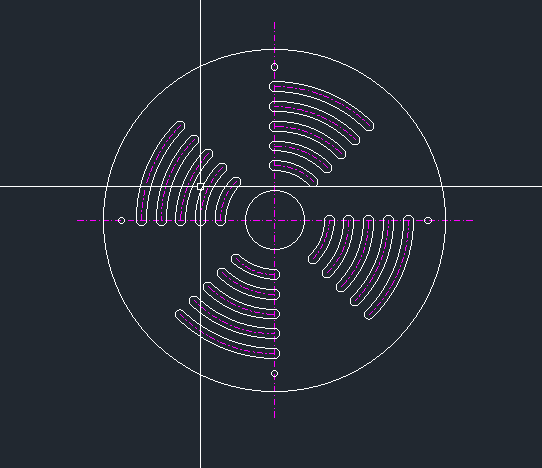
The device is simple, with 2 discs, one fixed in the pipe and a rotating one closing or opening radial oblongs (sketch attached).
001_b1xpzi.png


My issue here is how to determine the required area for the pressure drop, I'm studying some materials on the internet, but I'm still cant get the formula done to put in a sheet to evaluate all the required areas.
I have all the properties of the air in the required working conditions, I just didnt realize yet how the make the equation to get the required area for the pressure drop.

I've tried to use this material from NASA but I've get confused and my formulas didnt work.
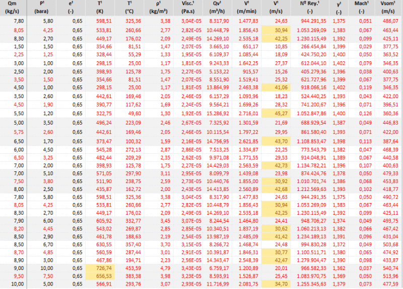
Below is one case:

D1 = 350 mm (pipe diameter before valve);
m1 = 7,8 kg/s (massic flow);
P1 = 5,8 bara (pressure before valve);
T1 = 325,36 °C (air temperature);
ρ1 = 3,38 kg/m³ (density before valve);
V1 = 24,63 m/s (air speed before valve)
γ1 = 1,375 (gamma factor Cp/Cv for T1)


Ao - ? (Orifice plate required area);

D2 = 600 mm (pipe diameter after valve);
m2 = m1;
P2 = 1 bara (atmospheric);
T2 = T1;
ρ2 = 0,58 kg/m³ (density after valve);
V2 = 47,76 m/s (air speed after valve);

Could someone give me a help with this equation ?

Thanks in advanced.

Barata
 
Replies continue below

Recommended for you

Well if this is a single device, one key issue you will face is that at a certain point, about 3bara, you will get choked flow in what is basically an orifice.

Then, apart from the noise the thing will emit, you run into a completely different set of equations and also the point where you change from one to the other won't be easy as you approach sonic velocity through your gap.

I think a better way might be a whole set of smaller tubes with some control valves / on off valves with maybe a set of multi orifice devices.

For the pressure range you have I can't see this being practical.


Remember - More details = better answers
Also: If you get a response it's polite to respond to it.
 
LittleInch, thanks for your reply, I just have a few comments:

Well if this is a single device, one key issue you will face is that at a certain point, about 3bara, you will get choked flow in what is basically an orifice.
Below are some examples of compressors with real operation conditions. The maximum mach number will be at 0,13, so it wont be in a critical condition (if i'm not mistaken).
002_m9wtpf.png

** in each 3 lines you can see the maximum, average and minimum working condition for some compressors**

Then, apart from the noise the thing will emit, you run into a completely different set of equations and also the point where you change from one to the other won't be easy as you approach sonic velocity through your gap.
Yes, the noise is another problem that we are trying to handle with acoustic specialists. Actually at the moment I still cant calculate by myself the noise in dB for this device.
By the way, I'm trying to calculate this area basically to get the minimum and the maximum required area, because during operation, the automation with all the instruments will make the control of the device (opening or closing) to pressurize the section before it. With the right equation I could put it in the sheet above and then get the max. and min. required area.


I think a better way might be a whole set of smaller tubes with some control valves / on off valves with maybe a set of multi orifice devices.
I agree, but this a project that we don't have money to use the best solution like pressure reducing valves (or even multiple control valves), so we are trying to create this "raw" device. Instead of plates with radial oblong holes, I could use only multiple hole, that was just the first idea.


Btw, its for a laboratory that will test compressor prototypes, so this device will be used just a few times per year (we estimate around 5 - 8 times per year).

Thanks again.
 
LittleInch, sorry about the last post.
I misunderstood you, just now I realize you were walking about the flow velocity at the orifice and not at the pipe before the valve. The mach number there would be over 2 in some conditions from the table in the previous post.

But even with that mach number only in the orifice, is it possible to determine only the pressure drop ignoring other changes ?

Thanks.
 
Would a normal muffler with a variable orifice to account for the different compressor sizes not be a better approach than reinventing the wheel?

Is the pressure and/or pressure gradient in the device critical to the operation of the compressor? I'm just curious as to why you're looking at accelerating the flow through an orifice to remove pressure and noise from an exhaust, when expansion of the flow's available volume would reduce both the pressure and noise.
 
Rputvin, this project is for a laboratory where we are going to test prototypes of compressors (from gas turbines), only the compressors. So if I'm testing a compressor which has 8 bara in the exhaust, I have to maintain a branch of the pipe pressurized to simulate a combustion chamber before the compressor, and then after the device/valve, exhaust to atmosphere. For now this is the only solution we've found to maintain the line pressurized, so we have to create that pressure drop and adjust it to the compressor being tested.

About the noise, the laboratory is inside an urban area, so we have to keep the noise below 60 dB next to other some administrative offices. Using the software from METSO e.g. the noise generated from a butterfly valve for these working conditions are around 105~115 dB. But not even one supplier here let me use a valve in these conditions and still guarantee its product. I still need to get the correct area for those working conditions so I can calculate the noise emission and then design the muffler.
 
Are testing the upstream compressors to the combustion chamber or the downstream power turbines?

Either way, what you are trying to do is create a single stage control valve with a very wide range of differential pressures and flows.

Not surprisingly you're finding this difficult.

BTW you can't get more than mach 1 through an orifice.

Any single stage orifice is going to make a humungous noise once it goes sonic and you'll find it difficult to muffle that.

If you're trying to do this cheaply, then I would use your variable orifice thing as fine control ( or a butterfly valve) and then come up with a variety of multi orifice stages to act as the gross pressure control ( maybe also gradually increasing in size between each orifice to reduce velocity and noise) and then just swap them out as needs be. you could probably end up with three or four interchangeable sections to deal with a smaller range of pressure drops and flows. Trying to make this thing all things to all men is where you won't get it to work. IMHO.

Remember - More details = better answers
Also: If you get a response it's polite to respond to it.
 
Pressure transducer, controller, and an appropriately characterized control valve? Maybe add in a header or a couple sizes if the loads are dramatically different. You should be able to have near infinite control on that orifice, and it won't rely on predetermined calculations that seem to be an issue working through. I'd bet the time you're spending on trying to determine the theoretical orifice would pay for the added control to find it empirically.

That's just an opinion looking at this without all of the details.
 
LittleInch said:
Are testing the upstream compressors to the combustion chamber or the downstream power turbines?

Either way, what you are trying to do is create a single stage control valve with a very wide range of differential pressures and flows.

Not surprisingly you're finding this difficult.
My mistake, I've said "I have to maintain a branch of the pipe pressurized to simulate a combustion chamber before the compressor", the right word is AFTER the compressor. I have to keep the compressor outlet pressurized to be able to properly read the data from the instruments. This is a laboratory to test only the compressor, neither combustion chambers or turbines will be tested.

LittleInch said:
BTW you can't get more than mach 1 through an orifice.

Any single stage orifice is going to make a humungous noise once it goes sonic and you'll find it difficult to muffle that.
I guess I'm realizing and accepting that after all the researches and help from you guys.

LittleInch said:
If you're trying to do this cheaply, then I would use your variable orifice thing as fine control ( or a butterfly valve) and then come up with a variety of multi orifice stages to act as the gross pressure control ( maybe also gradually increasing in size between each orifice to reduce velocity and noise) and then just swap them out as needs be. you could probably end up with three or four interchangeable sections to deal with a smaller range of pressure drops and flows. Trying to make this thing all things to all men is where you won't get it to work. IMHO.
As multi orifice stages, what do you really mean ? Would be like, some discs in series, the first with the biggest and the last with the smallest hole in the center of the disc?
The first Idea was to use 3 valves in series to get the pressure drop, but decreasing the pressure, the volume is bigger and the velocity almost the same in the 3 valves, because of that we were trying to create the pressure drop in a single device. But I really didn't consider the critical flow in the orifices, I'll make a new condition with 3 or 4 devices to get the results.
Then, if I consider orifices in series with subsonic speeds, which would be the equation to get the correct area for a pressure drop ?
Using interchangeable discs is a really good idea, but I would still need to calculate the area for the pressure drop.

Rputvin said:
Pressure transducer, controller, and an appropriately characterized control valve? Maybe add in a header or a couple sizes if the loads are dramatically different. You should be able to have near infinite control on that orifice, and it won't rely on predetermined calculations that seem to be an issue working through. I'd bet the time you're spending on trying to determine the theoretical orifice would pay for the added control to find it empirically.

That's just an opinion looking at this without all of the details.
Totally agree about the cost of our time trying to find a solution for this issue, but for now we are with some free time to make this studies, awaiting some documents to be approved.
The max amount we can spend with this device/valve is about $20.000,00, and some suppliers proposals for consolidated pressure reducing valves are around $50.000,00, that's our biggest problem, the project cost is restricted. And about the theoretical data, we need at least get the minimum and maximum required area and demonstrate it to the client, prooving that our solution is going to work in those conditions. And when we start up the laboratory we are going to get empirically the real data for each condition.


What I mean is a set of the following typicals.

Usually the first orifice will be smaller then gradually getting bigger. So long as the orifices are far enough apart, the pressure rebounds to a certain extent so you just need to play with a standard orifice calculation for on critical flow and put the results of the first one into the second one etc and avoid critical flow.

Orifice calculators abound on the internet.

Or ask a vendor to come up with some designs for a set range of flows and pressure drops.

you will need some sort of fine control such as a butterfly valve


section 4.1

One thing though - at 10 bar, you're going to need to make this out of something pretty strong and then pressure test it. Labs are a bit notorious for not always following the same sort of safety culture and practice as industry, in part due to this "it's only in use occasionally" thought process. It only takes one time to kill you.


Remember - More details = better answers
Also: If you get a response it's polite to respond to it.
 
LittleInch said:
Usually the first orifice will be smaller then gradually getting bigger. So long as the orifices are far enough apart, the pressure rebounds to a certain extent so you just need to play with a standard orifice calculation for on critical flow and put the results of the first one into the second one etc and avoid critical flow.

I did it now, considering 3 orifices in series the mach number in some situation are up to 0,7, so one problem solved, like you said, smaller orifice in the first device and big in the last, but the issue here (not exactly a huge problem), is that I have to define some pressure drop I want in the device then go to a specific software(using SF Pressurr Drop here), calculate the correct area for that pressure drop and then return to excel filling the cell with the area value. So it gives me a little bit of work considering I need to simulate many cases, its because of that I want to write the equation to get the required area automatically.
003_tuwvve.png


Thanks for the links, I've sent an e-mail to Doyeong and lets see if they answer.
Meanwhile I was trying to make the equation as shown in the link but the orifices areas/diameters I've got as result still doesn't match with my software and online calculators results. The file is attached here, if anyone have some free time to take a look please.


Orifice can't give you control. It can just hold pressure in your tube. As pointed out above, a butterfly valve will give you decent control. What I wanted to point out is that your discharge looks too high. In your excel sheet, you have calculated 7.8 kg/s of air (8000m3/hr of hot air) flowing through your exhaust. This appears to be a very large value. I used to work on an offshore installation, and the fuel flow rate to our 1MW gas engine was 60Mscfh, i.e., 1700m3/hr, at a pressure of 21 bars. The line was about 8 inch in diameter (I don't know exactly, but something like that). According to your excel sheet, your velocity before the orifice will be around 18m/s, which will be highly turbulent in 40cm dia pipe. As you go down, through orifices, and increasing the tube diameter, you will have lower velocities, and much lower Re number. Wherever you start getting laminar flow, you should place a movable disc in the tube (basically a butterfly valve). When you get a velocity of around 4-5 m/s, you can just use a diverging mouth, something like a draft tube.
One more thing you need to be careful of is that after expansion through orifice, air might get cooler, which will reduce it's density.

Hope this was useful. I know it's a very late post, and probably you have already done what was to be done. Please respond if you're still working on this. I'm curious what you've tried for controlling the pressure.
 
Status
Not open for further replies.
Back
Top