Continue to Site

Eng-Tips is the largest engineering community on the Internet

Intelligent Work Forums for Engineering Professionals

  • Congratulations waross on being selected by the Eng-Tips community for having the most helpful posts in the forums last week. Way to Go!

Required Member Stiffness to Brace CMU Wall for Stability in Out of Plane Direction?

Status
Not open for further replies.

Bisbee_Structural

Structural
Jul 15, 2021
17
US
We are removing an existing floor plate that braces a 12" thick CMU wall in the out of plane direction.

As a result the CMU wall's unbraced length will double and the wall will no longer work for wind loading.

I want to add a horizontal girt to stiffen the CMU wall at the same elevation as the removed floor plate. This girt will allow the unbraced length of the CMU wall to stay unchanged.

I cannot find any stiffness requirements for this girt to ensure it will actually brace the CMU wall- similar to the stability requirements for steel construction in Appendix 6 of AISC 360.

Does anyone have any references or experience with this issue?

Thanks in advance!
 
Replies continue below

Recommended for you

Is the wall filled and/or reinforced?

We do this sort of thing all the time, you just need to estimate the displacement of the wall and design something to suit
 
It's an older CMU wall (~60 years old) and according to our probes it's unreinforced and ungrouted.

I assume hollow CMU with face-shell bedding only.

With these assumptions the current wall works for gravity and wind but when it doubles in height the tension stress in the mortar is too great under wind.

I want to use a cast in place reinforced concrete girt. I assume a max allowable deflection of L/1000 for the CMU and currently have a 8"X10" girt that embeds 6" into the wall and sticks out 4".

Perhaps I'm over thinking it- could be that the mortar is so weak in tension that the girt will always take the load, in which case I don't think there will be much concern about the girt not being stiff enough.
 
There are a few ways to approach this and it depends what you're trying to accomplish.

My approach would be:

Provide a new system that has sufficient strength and stiffness to satisfy all design criteria you want this to achieve. Connect the CMU to your new system sufficient to take 100% design loads (whatever the applicable case is). So you might drill and epoxy starters out of the wall and into a new concrete wall.

This way you are certain you meet your design criteria regardless of the performance of the CMU.
 
OP said:
Perhaps I'm over thinking it

I don't think so, particularly with URM.

OP said:
Could be that the mortar is so weak in tension that the girt will always take the load, in which case I don't think there will be much concern about the girt not being stiff enough.

I disagree. Even if the girder does take all of the load, I don't see how that would equate to it being of adequate stiffness to preclude buckling.

OP said:
I assume a max allowable deflection of L/1000 for the CMU and currently have a 8"X10" girt that embeds 6" into the wall and sticks out 4".

If that L/100 is the lateral deflection limit then I agree that's probably adequate. Still, for something this critical, I'd prefer some method of checking that speaks directly to stability.

With your CIP girt inset into the URM like that, how will you maintain a positive, lateral shear connection between the walls and the girt, particularly for the upper wall?


Here's a proposed method. It's imperfect but will have to do until something better comes along:

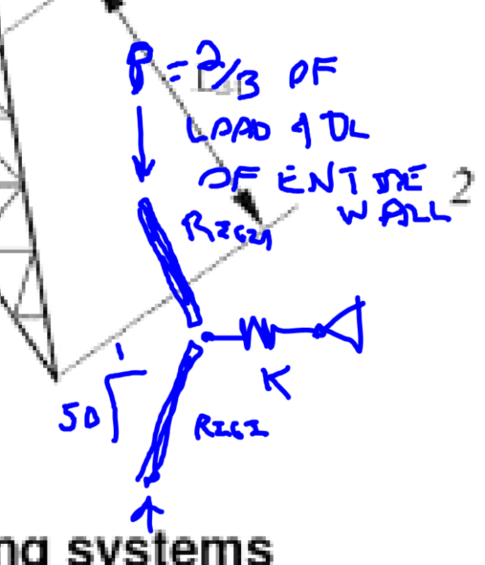
1) Model the upper and lower walls as rigid posts, hinged at mid-height and 2% out of plumb.

2) Apply 2/3 of the total wall weight and total load applied to the wall at the top of the model.

3) Work out the spring stiffness required for this to be stable.

4) Work out a beam stiff enough to serve as the equivalent spring to #3. Assume the beam to be laterally loaded at midspan.

This should at least serve as a decent barometer of the situation. If you meet this check in spades, sleep easy. If not, make the beam stiffer or find a way to refine the analysis.

One thing that complicates this check would be long term lateral creep in the girt. I'd be conservative in your estimates of that here.

c01_er8l6a.png
 
@KootK

Thanks for the thoughtful reply.

RE: the connection between the CMU wall and the concrete girt:

The structure will be fully shored at this location to remove floor loads from this wall. The wall will be laterally braced against out of plane movement.

The Contractor cuts a 6" deep chase into the CMU units where the girt will go, cutting thru the face and 6" of the webs. (am a bit unsure about this approach- my current assumption is that the shoring will prevent the wall from buckling while this chase is cut but am pondering how to demonstrate this)

The Contractor places mesh in the cells to keep the concrete from pouring down into the CMU cells below as much as possible before placing (4) #5 longitudinal bars and #3 hoops @ 12" into the chase and building out formwork to support the interior 4" of the girt projecting beyond the interior surface of the CMU wall. The girt is then cast w/ concrete poured in from the top of the 4" projection where the formwork is open. I've been assuming that the concrete will flow into an inch or so of the open cells of the CMU above and below the girt and this way engage the blocks, assuming this would form a better connection than your typical mortar bed joint.

The methodology you propose sounds reasonable- do you have a reference for the 2/3 load and the 2% out of plumb? Will also be careful about creep/shrinkage etc.

I spent quite a bit of time Friday looking for something about this topic in the US masonry codes & references I have and was pretty surprised to come up empty handed.
 
Bisbeee_Structural said:
...do you have a reference for the 2/3 load and the 2% out of plumb?

The 2% was homage to what we typically do for other materials such as steel. And I believe that this represents the origin of the "2% rule". I imagine that you've actually seen this wall and can, therefore, gage whether this is more appropriately a 2% situation or a 10% situation. I don't know that the final answer is even all that sensitive to this estimate. It's mostly just a perturbation to get the instability fun rolling.

I've got nothing for the 2/3 business other than "it makes sense to me". If you imagine each foot of wall as a vertical strip truly independent of its neighbors, then my method seems about right for the strip at the center of the girt. For the strips at the ends of the girt, I would expect those to produce no stability demand at all in the beam unless the beam supports themselves are flexible. Using 2/3, I'm basically ignoring the demand originating from the 1/6th strips of wall at the ends and overestimating the demand from the load in the middle 2/3. I feel that this puts things somewhere between "appropriately conservative" and "ridiculously conservative". I recommend that you give this some noodling to ensure that it speaks to your own intuition. When it comes to risking the lives of civilians, you probably shouldn't be just relying on the advice of some internet nutball.
 
Status
Not open for further replies.

Part and Inventory Search

Sponsor

Top