CDLD
Structural
- May 20, 2020
- 223
Hello,
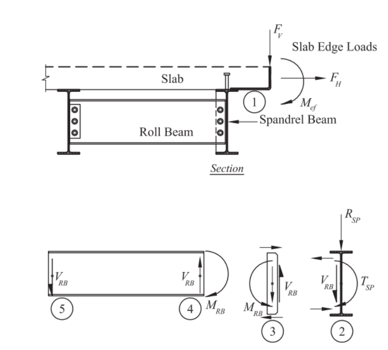
I am designing a beam that is carrying welded HSS stubs with a lateral load and moment (causing torsion in the beam).
We intend to brace for the torsion using infill beams with simple shear tab connections.
In the attached PDF, are the stiffeners required to resist moment in Case 2 like they are in Case 1?
And if so, what would the moment on the stiffener be in Case 2?
Thanks,