Continue to Site

Eng-Tips is the largest engineering community on the Internet

Intelligent Work Forums for Engineering Professionals

  • Congratulations KootK on being selected by the Eng-Tips community for having the most helpful posts in the forums last week. Way to Go!

Restrained Retaining Wall Analysis 1

Status
Not open for further replies.

MILRAD

Structural
Feb 2, 2020
18
I have been modeling restrained retaining walls in EnerCalc with the attached geometry. (I hope I uploaded the figures correctly.)

EnerCalc has two options - one where the wall is pinned-pinned and another where the wall is fixed-pinned (fixed at the footing).

When I run the model as pinned-pinned I get the attached results. All of these results make sense - the moment and shear in the wall, the reaction at the top, and the bearing pressure. The triangular distribution of bearing pressure is because of the moment caused by the unequal weights of the soil over the toe and the soil over the heel.

When I run the model as fixed-pinned I expect to see a triangular distribution of bearing pressure to resist the moment caused by the unequal weights of soil and the moment from the the lateral load of the soil less the moment from the reaction at the top (the end moment of a propped cantilever). Instead I get an uniform distribution. The resultant of the bearing pressure equals the weight of the soil, footing, and wall. The reaction, shear, and moment in the wall are what you would get from the statics of a propped cantilever beam with a triangular load.

If I change the lateral pressure and/or the density of the soil I will get the same type of answer - a uniform distribution of bearing pressure equal to the weight and the moments and shears for a propped cantilever.

What am I missing or are the results wrong and the bearing pressures should be triangular?


 https://files.engineering.com/getfile.aspx?folder=a286cbd2-d899-4781-989a-9555eb9ac1eb&file=Restrained_Retaining_Wall.pdf
Replies continue below

Recommended for you

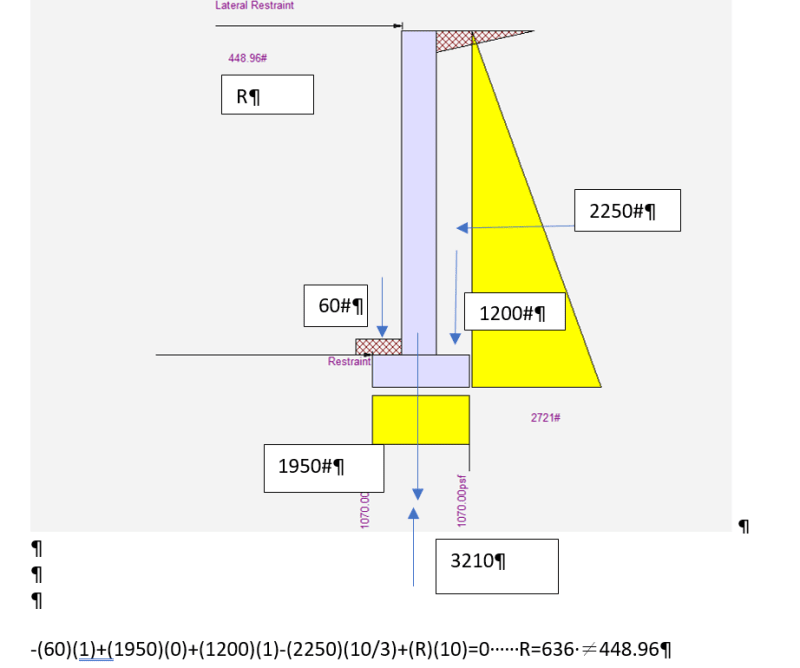
In the fixed-pinned model the moment caused by the soil surcharge that was resolved by unbalanced bearing pressure is now resisted by the footing-foundation joint and resolved by a horizonal couple over the full wall height.
 
Screenshot_2023-03-15_142509_m0sbgn.png
 
Statics_sni94c.png


I am not following. Are you saying this is what the freebody diagram would look like? The 448.96# is close to the 450# expected for a propped cantilever.

If I cut a section where the wall meets the footing there needs to be a moment of 3000#-ft for the upper reaction to be 450#. Wouldn't this moment be applied to the footing plus the vertical weights and be resisted by the soil?

I am just not seeing the equilibrium.

It also feels like you are assuming the soil is rigid for the fixed-pin case and not rigid for the pinned-pinned case.

Sorry if I am slow. Thanks for any help you can give me.
 
Pinned-Pinned:
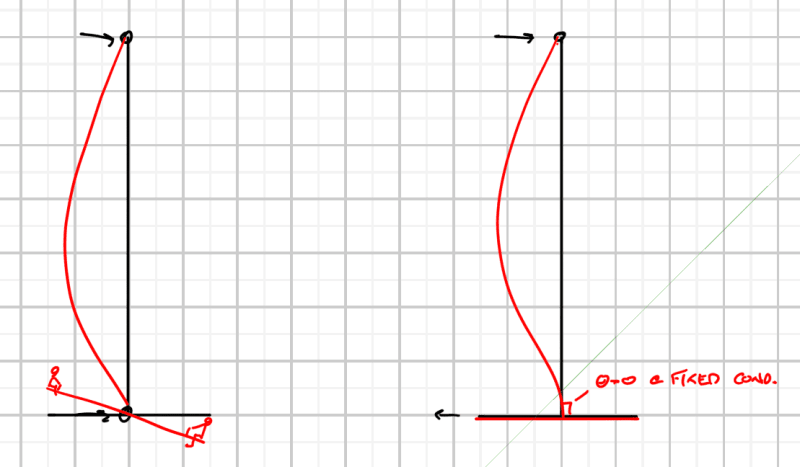
The foundation is free to rotate independently at the pinned joint between the wall and the foundation. Since rotation is free the unbalanced earth pressure on the heel and toe results in the triangular bearing pressure. Said another way the unbalanced earth pressure forces the heel further into the soil mass then at the toe and p=k*delta so the soil spring reaction varies.

Fixed-Pinned:
The fixed joint between the foundation and wall is not able to rotate, theta=0, if the joint cannot rotate then the foundation cannot rotate and instead presses into the soil mass as a rigid body so delta into soil is constant, p = k*delta = constant.

 
OK. I now see there is no rotation of the foundation resulting in uniform bearing pressure.

Shouldn't the reaction at the top (and bottom) be different than for a propped cantilever? I am still not seeing how there is equilibrium.

Thanks
 
In my opinion, the fixed condition is more appropriate for piles rather than soil. The bearing pressure is constant and would be resolved by an up-down force at the footing resisted by piles with the moment arm being the distance between them.

MILRAD said:
Shouldn't the reaction at the top (and bottom) be different than for a propped cantilever?

No, because that's exactly what it is. The fixed-pinned option would design it as a perfectly rigid propped cantilever. If you want the moment to go into the footing and resolve into the soil, you'd have to make use of the soil subgrade modulus, which would either require someone smarter than me or FEM software. The soil bearing reaction would be something between the triangle and the uniform rectangle.
 
I just noticed Celt's little teeter totter on the pinned condition foundation lol.

I would only use fixed if I had piles, a large mat foundation, or a relatively large heel.
 
Actually, to amend the last part of my statement, I take that back. The pin-pin should already assume a perfectly rigid footing. So yeah, it's either on soil or piles (or large mat foundation/large heel as driftLimiter suggested).
 
I can add some first-hand experience to this discussion. In the interest of full disclosure, I work for ENERCALC.

First I'll say that retaining walls are a real bear if you think you can apply loads and logic and come out with a perfect balance of forces at the end of the analysis. Hugh Brooks's book Basics of Retaining Wall Design does a really nice job of explaining how the industry eventually got to the point of just enveloping the design and allowing designers to sleep well at night. Current design methods produce results that are consistent with what we all would sketch up on the back of a napkin and call "typical". This demonstrates that our minds have grown accustomed to the designs produced by these methods, even if they don't allow us to draw a freebody diagram and demonstrate exact equilibrium. The bottom line is that these methods are proven, accepted, and understood by contractors.

The next fun topic is factored loads for soil pressure. Some designers factor up all of the applied loads and run the analysis at the strength level (yet another potential contradiction, because it may not be possible to demonstrate that the system is stable under strength-level loads). Other designers apply service-level loads, perform the analysis, and then use some method of factoring up the soil pressure to strength-level. (ENERCALC SEL uses the second method.)

Oftentimes, a heel will be designed for the weight of the soil on top of it plus its own selfweight, but the upward force of any soil pressure under the heel may be conservatively neglected. But that design moment in the heel won't result in equilibrium with the moment from the toe and the stem, because it has been taken out of context. It just makes design a lot easier.

Now for the actual question about soil pressures under restrained retaining walls...

A restrained retaining wall with fixity between the footing and the stem is indeterminate. As the at-rest pressure goes to work on the stem, it's obvious that the horizontal reaction at the top of the wall will increase. If the stem and stem-footing joint are very stiff, they will significantly limit stem deflection and rotation of the stem-footing joint, resulting in a nearly uniform soil bearing pressure. (This is the assumption that is being applied in ENERCALC SEL.) On the other hand, if the stem is flexible enough, there may be bending deflection in the stem, resulting in the tendency for some rotation at the stem-footing joint. If the joint is truly rigid, it will pass that moment on to the footing to be reacted out as a variation in the soil bearing pressure.

Hopefully that helps to explain the thought process behind the current logic.

Director of Engineering
ENERCALC, LLC
Web:
 
Good stuff Chris. I've designed or checked hundreds of retaining/basement walls on Enercalc so I'm glad I can still sleep well at night.
 
Status
Not open for further replies.

Part and Inventory Search

Sponsor