Greetings.
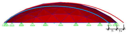
I am in the process of checking the calculations of structural grid structure of several domes (Fig. 1). I have almost no experience in designing such structures because I am designing other structures, like industrial buildings, storeys, etc.
I am creating my calculation scheme and I have encountered that there are huge forces from temperature in the perimeter elements. The structure is inside the building, so the temperature will be kept around 20 degrees Celsius all year round, but since the dome is glazed, the sun's light will heat the structure. The heating temperature is +50 degrees Celsius, according to the norms in my country. This value is derived from the worst case, when the structure is fully mounted in cold season, then summer comes and the structure is under sunlight.
The supports were modeled in two ways:
1. Fixed by XYZ (Fig. 2).
2. Fixed only along Z and in the direction perpendicular to the perimeter (Fig. 3).
What are ways to get rid of temperature forces in such structures in perimeter elements?
Is it possible to mount the structure without perimeter elements and close the temperature contour only when the temperature is close to the operating temperature, so that the temperature difference is minimal and the forces are not so large?
What solutions can be for a round in plan dome (Fig. 1) and for a complex in plan dome (Fig. 4).
I am interested in the opinion of those who design such structures: would it be legitimate to get rid of part of the temperature load in the way I described above or are there other ways or simplifications. I am also interested in the methods of assigning bearings, both in the program and their realization in the construction.