Continue to Site

Eng-Tips is the largest engineering community on the Internet

Intelligent Work Forums for Engineering Professionals

  • Congratulations cowski on being selected by the Eng-Tips community for having the most helpful posts in the forums last week. Way to Go!

Result Calibration Singularity

Status
Not open for further replies.

EngineerMickeyMouse

Structural
Jan 15, 2015
44
Hi folks,

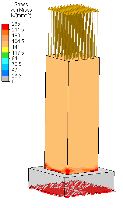
This time I would like to ask about your opinion.

Below figure is self-explaining, you may notice 150 MPa applied to the tip of smaller solid object (lets assume it is mild steel) and below, larger box is providing supports. Assuming it is converged enough, in this simple example it is obvious real structure will "see" stress about 150 MPa in zone abutting to the larger object. But if the geometry would be more complicated, how would you be so sure how to get rid off this singularity? In other words, how to convince somebody that looking at stress range singularities are not real? I prefer to use stress linearization. What is your opinion? Please share.

Test1_oywoav.png
 
Replies continue below

Recommended for you

How do you know it's not real? If the base is soft and somewhat compressible, then one might see stress concentrations in the top part.

TTFN (ta ta for now)
I can do absolutely anything. I'm an expert! faq731-376 forum1529
 
IRstuff, thanks for this question. Assumption is that larger part is the same material, i.e. mild steel. Therefore applied 150 MPa stress at the tip in reality will simply be exposed at larger area for bottom part, hence stress will be lower. Please note, force is tensile not compressive. What do you think?
 
I don't know enough to say; I only speculate that the bottom piece's top surface is bowing (concave up), which would result in the top piece showing higher compressive stress in the corners and edges.

What is the material of the bottom? Have you tried to make it infinitely stiff?

TTFN (ta ta for now)
I can do absolutely anything. I'm an expert! faq731-376 forum1529
 
Exactly same material a s for top part, it is mild steel yield strength 235 MPa.
Did not make it stiff since it will not assist with answering my original question, and therefore it could not be applied for more sophisticated instances then.

Please look at this problem in this way: from strength of material you are 100% sure stress in the assembly will not be much above 150 MPa, but as FEA is a tool which brings in mathematical artefact in form of singularity, these singularities are "littering" true values and the question was how to explain this in professional way to someone. In my case, I think graph plots which are presenting immediate peak will explain why we may rid out of this values much above 150 MPa. How would you get rid off these singularities to report possibly accurate stress?
 
sorry but where's the singularity ?

There's a modest stress peak in the corners. ok, may be real. certainly the assumption of constant 150 MPa = applied load over the same foot print is abit ... simple. It doesn't sound unreasonable to me that the reaction would be non-uniform, as the baseplate that isn't being compressed is behaving different to the part being compressed. particularly if you're looking at von mises stress ... maybe you've got tension and compression principal stresses ?

another day in paradise, or is paradise one day closer ?
 
You have to consider the relative stiffness of the block to understand the stresses. At the edge of the block the stiffness is less than in the centre of the block and so deforms more and stresses are higher. At the corner this effect is compounded and together with the stress concentration effect of a right angled corner, the stress is higher. I wouldn't necessarily use stress linearisation but generally look at the stress distribution up to the corner, which may be parabolic in nature. It's what you do with this stress that is in question. In general stresses at these 'singularities' wouldn't be of concern unless you were looking at fatigue damage.

 
EngineerMickeyMouse
Your Problem dissection-
1) There is abrupt change in cross section of the component at the junction of base plate as well as no smooth connection with fillets. This would be starting point of stress concentration.(Concentration Factor=235/150=1.5667). (This would change internal stress lines at the junction and concentrate these stress lines at this junction hence stress concentration)

2)If you assume the relative stiffness of the both bodies, the base plate stands out as more rigid candidate which is intensified by fix boundary conditions. This will resist the elongation of the connecting nodes of the members and you will see the high stresses in the connecting region.(The end face nodes will see more resistance and give singularity stress at the face itself if you have fixed the face of long member. Fixed face will now behave like rigid face)

3)In reality there will be high stress at these regions close to yield(sometimes crossing the yield)which is why if fatigue is expected as pointed out by corus, you cannot ignore these stresses. Anyway you should not ignore any peak stress blindly.

4)Stress linearization is good option to separate out peak from the average stress at this section. You can then find out from handbooks/theory/paper what is the stress concentration factor and compare your results with this and provide your client this calculation.

If you and the client knows the basics, you will find no difficulty in convincing about the stress singularities. But if not(mostly they act innocent[evil]), you can provide your understanding in detail like explained as above.


Hi
I don't think it is a singularity att all.

You load the top part to have a stress of 150 MPa. Since the bottom part is larger the same load will result in smaller stresses/strains in that section. And that difference is more pronounced in the corners. That is because the stress will spread in two directions in the corners while it only spreads in one direction along the inner sides.

So the top part will experience the corners as stiffer supports and this results in higher stresses.

Is it clearer och just more confusing [smile] ?

Regards

Thomas
 
Thank you all for your inputs. Good to discuss.

Since I do not have welds in the model, sharp corners (and stiffness at corners you all mentioned)are influencing load path.
In the same time convergence study shows as expected that those corners/edge values are hitting infinity and this is singularity.

So maybe I will ask you, were there instances in your experience that you included welds in your 3D FEA model too? Please note I am not asking about fatigue calculation.
I am curious what is your good practice.

Thanks for further responses. Appreciated.
 
Hi
I missread the problem because I thought the detail was in compression. On the other hand, if you don't use welds and the load path is the entire contact surface. Then there should be no difference.

You mention corner values that are infinite but your plot shows peak values of ~235 MPA with a load level of 150 MPa. What type of data does the figure show, exactly?

How have you postprocessed the data? First I would skip von Mises and use normal (vertical) stresses.

Regards

Thomas
 
Sorry for misleading legend description. I have noted "von Mises" at the figure, when in fact there shall be "normal stress". Normal stress is used all the time, no von Mises. Once again sorry for this misleading description at a figure.
235 is the cut off value manually input to adjust stress contours to be more visible, but normal stresses are much larger than 235 and goes up along with down sizing mesh.
Case is tensioned, not compressed.

At objects' edge, where the geometry change is made, normal stress nodal value consists of sum of: (A) Real 150 MPa of the applied force + (B) Real Concentration stress due to geometry change [would be visible if weld would be modelled precisely) + (C) Unreal Peak stress due to singularity.
The question is how do you estimate B and C in simple model I have proposed under consideration. Perhaps it is not achievable in practice without welds modelling.
 
I have yet to meet a welder who can make a weld 'precisely' so modelling a weld precisely would be not serve any real purpose. In general the stresses you obtain are compared against design limits. These may be the mean stress or bending stress, in simple terms. For a weld the stresses are compared against SN curves to look at fatigue damage, and these SN curves are obtained from nominal stresses close to the weld. Some look at the stress distribution up the juncture and ignore any stress concentration effect to obtain this 'nominal' stress so that a conservative result is obtained. If you want the average stress in the weld over the throat thickness, then looking at the reaction forces at the juncture is a reasonable method.

 
EngineerMickeyMouse said:
The question is how do you estimate B and C in simple model I have proposed under consideration.

My earlier post gives answer partly to your above question. You can use either stress linearization or average nodal/reaction forces at the point of interest as pointed out by corus also to get average stress which matters than singularity stress or stress concentration if no fatigue is expected.

Another thing I mentioned is you can get the stress concentration factors which may be available for some simple geometries and use it for comparing the stresses at the junctions. About peak stress due to singularity, you can check whether you have any modelling errors or analysis assumptions such as very sharp corners(I guess modelling the weld can minimize singularity stresses and you have more realistic stress), mesh sizes at the junction, contact non-linearity, altering boundary conditions(such as applying forces on the face or no of nodes rather than single node), Hertz contact stress etc. Altering all above factors may help in reducing the singularity stress.

Keep in mind that what you are doing is rather simple problem and you should get reasonable amount of peak as well as singularity stress that you can at least predict approximately(with engineering judgment and logic) or expect inherently available since FEA is approximate method. But if you are getting very high stresses that are logically cant be expected for loading conditions considered then don't you think you are making mistake in your assumptions.
 
Another way of looking at it is that if the normal stress was unchanged at the change of section, then adding material has had no effect on the normal stresses. You can then carry this argument through to the lowest extremity, which is absurd, since if the height of the wider base is enough, the normal stress must reduce to A1/A2*s1.

Cheers

Greg Locock


New here? Try reading these, they might help FAQ731-376
 
"weld" is sometimes used in describing FEMs to show that nodes are shared between different pieces when they share a common face (as opposed to a physical weld).

another day in paradise, or is paradise one day closer ?
 
Status
Not open for further replies.

Part and Inventory Search

Sponsor