Eng-Tips is the largest engineering community on the Internet

Intelligent Work Forums for Engineering Professionals

Retaining Wall Base Crack Pattern 4

Status
Not open for further replies.

Nick6781

Structural
May 15, 2024
14
0
0
CA
Hi Everyone,

I have some questions regarding this previous discussion:
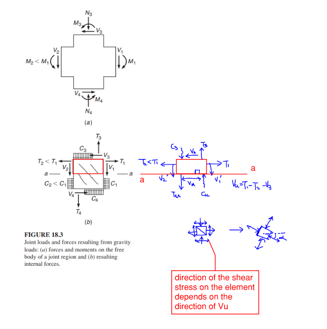
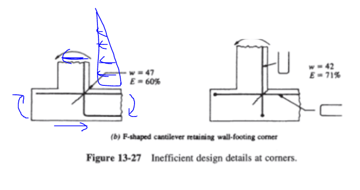
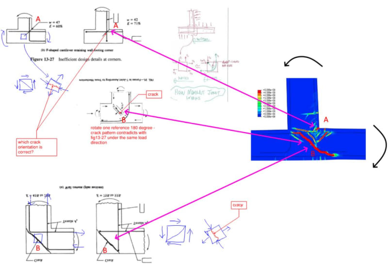
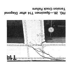
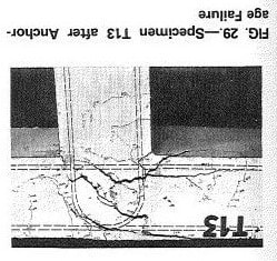
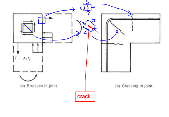
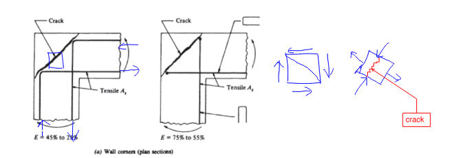
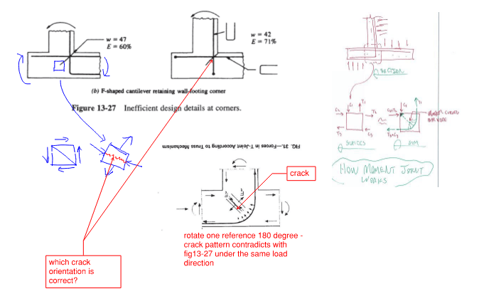
Navigating the various references in the post, I tried to understand the crack pattern at the intersection between the retaining wall and the footing. Using plane stress transformation from what I could remember from the mechanics of materials, I focused on a small square element within the moment transferring joint and tried to find the orientation of the diagonal tension. Most of the crack patterns I got conform to the corresponding references, except one. Additionally, one reference seems to contradict the other in terms of the crack pattern. Please see the pictures below.

I would appreciate any help.

Thanks,
Nick


1_dc7rfi.png
2_s2daba.png
3_gyxad4.png
 
Replies continue below

Recommended for you

I love this particular grenade every time it shows up

That being said, I don't think the two are directly comparable. The location of the cracking being looked at is different (at the opening corner vs inside the bend radius) and the reinforcement configurations aren't the same (the direction and/or lack of a bend, the presence of the horizontal reinforcement)

----------------------------------------------------------------------

Why yes, I do in fact have no idea what I'm talking about
 
I studied this grenade for a bit per Nilson's Design of Concrete Structure 14th Ed Chapter 11. The book says a (moment transfer) joint will develop a pattern of diagonal cracking owning to the diagonal tensile stresses that result from the normal forces and shears.

Typically, a joint is not in pure bending — there might also be shear and normal forces, see the figure below. The direction of the internal shear at section cut a-a is unknown, as it depends on T1, T2, and V3. Looking at a small element at the boundary of the section cut a-a, the direction of the shear stress on the sides will determine the direction of the crack (diagonal up or down), and the magnitude of the shear & normal stress acting on it will determine the angle of the crack with an orthogonal axis.

Referring to the figure I had a problem with, I suspect the test engaged a shear force similar to what a typical retaining wall would experience. Maybe the graphic just didn't show the shear force. The direction of the internal shear within the joint decided that the crack pattern would be like that.

4_yanlt3.png


5_wbiirn.png
 
At the risk of venturing back into dangerous territory, I'd like to add my two cents. You have a crack at the inside of the joint attempting to tear open (call this Crack A). Additionally, there is a perpendicular crack through the middle of the joint caused by a busting force from the compression bottle strut (call this Crack B).

Since the forces are turning the corner, the principal tensile stresses are not uniform throughout the joint, making it not a matter of one crack being correct over the other. Both crack tendencies exist in different sections of the joint, and the diagrams you show are considering each crack separately, depending on which is the critical one in question. I have reoriented your diagrams so they are all matching and have also added an extract of a finite element model of a similar situation, illustrating the two different cracks.


WALL_ni71ub.jpg
 
For the sake of completeness, what does crack B look like in the model if the reinforcement bend points in the other direction?

----------------------------------------------------------------------

Why yes, I do in fact have no idea what I'm talking about
 
That FE model was from a paper.

Here’s the experimental case where the legs turn back across crack B. Slightly better performance.

IMG_4028_uzup5k.jpg
 
Having done a deep dive on this topic, in large part thanks to these threads and some of the good technical papers that have been posted here before, I'm left with a bit of concern when I come across certain designs of rigid moment connections in RC structures in my work. Often things I'm asked to review. More often than not, my impression is that the majority of designers will simply anchor the bars (not particularly concerned about which way the hooks go), and call it a day. Often there are no diagonal bars across the joints, no haunches, no reinforcement to control splitting/bursting through the diagonal strut, etc. etc. And almost certainly these are never analysed and designed based on strut-and-tie principles. If these walls were actually tested to their ultimate capacity, I bet most wouldn't reach anywhere near it.
 
I do agree with most who say the detailing is not proper. But my counter is that how we design retaining walls, it is a pretty conservative method and thus why it has not become an issue.

If you want to make thinner walls and use some new method to analyse/design them. Then yes you need to be concerned.

 
Status
Not open for further replies.
Back
Top