Continue to Site

Eng-Tips is the largest engineering community on the Internet

Intelligent Work Forums for Engineering Professionals

  • Congratulations Toost on being selected by the Eng-Tips community for having the most helpful posts in the forums last week. Way to Go!

RETAINING WALL DESIGN FOR RAILWAY LOADS 3

Status
Not open for further replies.

alumpkin

Structural
Sep 11, 2000
69
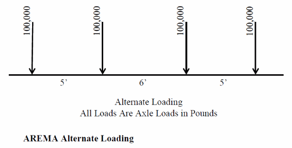
LOOKING FOR SOME CONFIRMATION THAT RAILWAY LOADS FOR A COOPER E-80 IS SIMPLY POINT LOADS BEHIND A RETAINING WALL. I CANNOT FIND ANY RULES DICTATING ANY GUIDELINES. SO, I AM USING A COOPER E-80 POINT LOAD (60K) 1 FOOT BEHIND WALL PLUS ANOTHER POINT LOAD (60K) 6 FEET BEYOND THE WALL FACE (5 FEET BETWEEN LOADS) AND THEN ANOTHER POINT LOAD AND THEN ANOTHER POINT LOAD ALL OF WHICH ADD THE OVERTURNING MOMENT IN THE WALL. THESE POINT LOADS ADD TO THE ALREADY IN PLACE BACKFILL LOAD. THERE IS A LOT OF OF INFORMATION ABOUT LOADS RUNNING PARALLEL TO A RETAINING WALL WHERE YOU USE 1800 PSF OR FOR AMTRAK APPROX. 2700 PSF DUE TO THE 50% INCREASE FOR IMPACT BUT I SEE ALMOST NO INFORMATION FOR LOADS PERPENDICULAR TO THE RETAINING WALL OR ABUTMENT.
 
Replies continue below

Recommended for you

Three suggestions:

1. The assumed active earth coefficient (Ka = 0.5), means the soil friction angle (φ) = 19.5 degrees.
φ = 19.5 degrees is consistent with backfill being "soft, packed mud". Not what I would expect to use as backfill.
This assumption is likely the primary reason the wall loading seems extremely high and the wall is 5' thick. A value of, say, φ = 34 degrees (making Ka = 0.28) may be a better choice.

2. Cooper loading is uniform distributed load (UDL), as GeoPaveTraffic first mentioned. The wheel positions shown in the sketch were used by Theodore Cooper, circa 1900, to simulate a UDL. They were never intended to be used as actual point loads for design. On soil, I would use the UDL (Cooper E-80 = 1780 PSF). The UDL loading is applied directly under the footprint of the crossties... assumed to be 9' long.

3. Point loading from actual wheel positions or the "Alternate Cooper E-80 Live Load" is appropriate for the short-span structural steel design crossing the unloader. The "Alternate LL" simulates the the junction of two fully loaded (Cooper E-80 rated) rail cars. This is the concept that Oldestguy mentioned in his post.

Alternate_Cooper_LL-1_rkpdqp.png


The two-car loading combination is higher than a single large 6-axle locomotive, like the General Electric AC6000CW. CSX uses 4 of these locomotives to haul 80-car unit coal trains to our (electric utility) generating stations.

GE_AC6000CW-1_yjrer6.jpg


For multiple locomotives, probably a good ideal to look at the wheel loading on structural steel from the junction of two locomotives. Doubt all 6 axles (3 from each locomotive) would be on a span at the same time.


Because of the critical importance of timely fuel (coal) delivery to operating generating stations, we did our major unloader upgrades (including planning, design, and construction management) 100% in-house. The attached photo shows one of my structural steel replacement/upgrades to make a 1960's unloader capable or carrying 21th century unit trains:

Rail_Car_Unloader-1_hxr1p8.jpg


I assume the unloader being discussed in this thread is a "bottom-dump"... a rotary unloader is a different animal.


[idea]
[r2d2]
 
Guys,

Thanks again for all of the insight.....much appreciated.

Alan Lumpkin, PE, MS

Alan L. Lumpkin, MS, PE
Greenville, SC
 
Status
Not open for further replies.

Part and Inventory Search

Sponsor