Continue to Site

Eng-Tips is the largest engineering community on the Internet

Intelligent Work Forums for Engineering Professionals

  • Congratulations waross on being selected by the Eng-Tips community for having the most helpful posts in the forums last week. Way to Go!

Retaining wall Design (Quick Question): Coulombs Theory 5

Status
Not open for further replies.

kellez

Civil/Environmental
Nov 5, 2011
276
Hi everyone, I am having a debate with another engineer and i want your thoughts.

I am using Coulombs Theory to calculate the Total Active Pressure, Pa acting on the retaining wall shown in the picture.

1st step:
calculate the coulombs active pressure coefficient, Ka which is 0.556

2nd step:
calculate the Total Active Pressure, Pa:
Pa = 0.5KaγH[sup]2[/sup]

Ka is the coulombs active pressure coefficient = 0.556
γ is the unit weight of retained soil = 20kN/m[sup]3[/sup]
H is the height of the retained soil

My question is, what shall i use for height of the retained soil, H in the equation above? H1 or H2 (see picture)
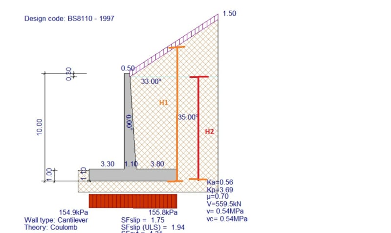

SAVE_20200129_135342_cxxplm.jpg
 
Replies continue below

Recommended for you

What friction angle for soil and wall in your cal?

Were you use soil friction angle 35°, slop 33° from horizontal? I'll try it later.
 
IDS,

I got the number as yours but it's a mistake - forgot taking the square root in the bracket in the denominator of the equation. The correctly calculated Ka is 0.552, which is quite close to the OP's 0.556.

 
Just for curiosity, I calculated Ka for wall frictions 18° and 26°, and the results are 0.5 and 0.517 respectively, both are lower than the Rankine's Ka, which is 0.542 (a mere 2% lower than Coulomb's with 35° wall friction). I started to doubt that is coulomb's theory suitable for cantilever retaining wall. Maybe someone can provide more insight to this topic.
 
Rankine is a more conservative approach due to its assumptions, mainly:
1. The resultant of the shear forces that act on the back of the wall are parallel to the backfill surface
2. The mobilized interface friction angle is ignored
3. The backwall geometry is vertical.

Rankine does not apply to irregular backfill surface (broken backfill) and point or distributed loads. Coulomb handles the mobilized interface friction angle, arbitrary backfill geometry, and non-vertical walls.
 
retired13 said:
I got the number as yours but it's a mistake - forgot taking the square root in the bracket in the denominator of the equation. The correctly calculated Ka is 0.552, which is quite close to the OP's 0.556.

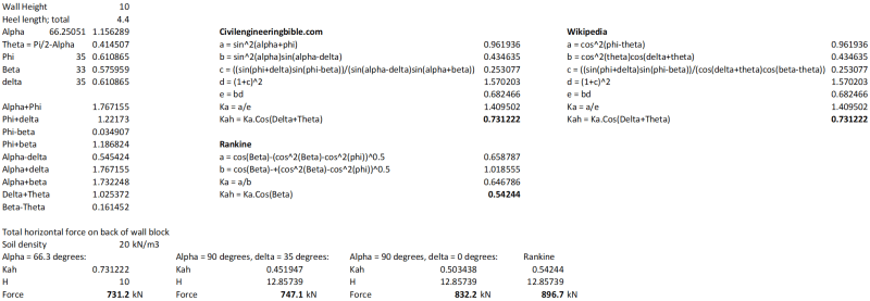
I think my numbers are right, I checked them using two different versions of the Coulomb equation, and the results agree with published tables. Are you taking the back of wall angle as the slope from the back of the heel to the back of the top of the wall?

I did make one correction though. In my earlier number I took the heel length as 3.8 m, but it should be 3.8+0.6m, which gives a Ka of 0.73.

I have attached a copy of my spreadsheet, and a screen shot below.

I have added total horizontal force calculations for:
1) Wall angle, alpha, as described above = 66.25 degrees.
2) Vertical wall, alpha = 90 degrees, with H = height to top surface at the back of the heel; "wall" friction = 35 degrees.
3) As 2) but wall friction = 0
4) As 3) but using Rankine Ka

Note that 1) and 2) give very different Ka values, but the forces are quite close, with 2) being slightly more conservative.

Also note that these calculations are for the total force on the wall. For calculating the force on the wall stem the failure plane would start at the bottom of the stem, so the alpha angle would be the angle of the face of the concrete.

By the way, I very rarely do cantilever retaining wall design (I usually work with MSE walls), but when I do I have used the Rankine equation in the past.

Coulomb_nnrv5t.png


Doug Jenkins
Interactive Design Services
 
IDS,

You are correct. Slop of the wall should be from top of the wall to the back of the heel. I was using 90° as usual - big mistake. Thanks for pointing out.
 
Are there any conditions where the Rankine approach is prescribed in lieu of the Coulomb approach?

Dik
 
dik said:
Are there any conditions where the Rankine approach is prescribed in lieu of the Coulomb approach?

The Australian retaining wall code has a table listing appropriate techniques for determining soil pressure under different circumstances.

Rankine and Coulomb both get a tick for simple cases, but for anything with any complications Coulomb is preferred.

I think it's interesting that the diagrams illustrating the Coulomb approach always show a solid gravity wall with no heel, and a near vertical rear face. In my searches today I haven't seen a single example with a cantilever retaining wall illustrating a Coulomb wedge.

It's almost like no-one is quite sure how to apply it to cantilever walls.

Doug Jenkins
Interactive Design Services
 
steveh49 - Good book. I'm not sure if I agree with the conclusion about using Rankine's method if the line doesn't intersect the soil surface, but it may be a reasonable approximation.

These day's I'd suggest varying both angles to find the lines that generate the maximum force.

Doug Jenkins
Interactive Design Services
 
dik said:
Are there any conditions where the Rankine approach is prescribed in lieu of the Coulomb approach?

I’d use Rankine when I need to do quick checks in the field or in meetings since it’s quick and easy. I’d use coulomb when working from my desk since it’s more realistic than Rankine (which is very conservative).
 
That was the answer I was looking for... thanks MTN...

Dik
 
kellez said:
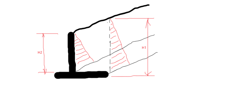
Please have a look at the two pictures below, its the same wall however in the second one, i highlighted the retained soil above the heel just to show what would happen if the highlighted section was also concrete? (it is said that the retained soil above the heel inside the virtual plane is assumed to be part of the wall)

What you have drawn indicating Rankine state (note that this failure mechanism is incomplete per Coulomb's perspective), in which, the wall and the soil on top of the heel is treated as a monolith, to resist the earth pressure caused by the failure soil wedge to its right. Yes, you should use the height between the heel and the sloping ground for earth pressure calculation to check stability of the monolith, however, you should only use the stem height in calculating earth pressure for the design of the stem. The important thing is, if you elect to use this method, you shall calculate Ka per Rankine's equation, not Coulomb's as in your opening statement. The graph below speaks my point.

rankine_iey9qv.png
 
Thank you everyone for your responses. So in summary, the virtual plane is only assumed if you are using Rankine theorem, where's Coulombs assues a wedge behind the wall.

 
I'm having trouble understanding some of the replies here, and I realize people note that textbooks and manuals don't often show Coulomb theory with cantilever walls but I still want to make sure everyone understands this: Rankine OR Coulomb can be used in cantilever wall applications.

I think Coulomb is shown on oddly shaped gravity walls in textbooks and manuals so often because they want to demonstrate how to use it on irregular wall shapes.

Coulomb is more accurate with active pressures but is not recommended for passive pressure since it could over-calculate the passive resistance.

I hope that clears things up a bit.
 
Status
Not open for further replies.

Part and Inventory Search

Sponsor