Continue to Site

Eng-Tips is the largest engineering community on the Internet

Intelligent Work Forums for Engineering Professionals

  • Congratulations waross on being selected by the Eng-Tips community for having the most helpful posts in the forums last week. Way to Go!

Retaining wall loads due to culvert

Status
Not open for further replies.

Usman Tanveer

Civil/Environmental
Sep 16, 2022
13
Greetings All , I have attached a picture of a culvert supported by retaining wall. The culvert has 6 m fill on top of it including a roadway. What should be the surcharge? in other words what loads should i consider . Should i include the weight of culvert ,water in culvert , fill on top of culvert and live load surcharge ,all of it?
 
 https://files.engineering.com/getfile.aspx?folder=9b8ce695-ae76-4482-89c4-38d2a8f2efc1&file=Bridge.png
Replies continue below

Recommended for you

I'm not clear on the configuration. In your attachment what is the culvert, and what is the retaining wall? What kind of culvert is it (concrete box, concrete pipe, metal box, metal pipe, etc.)?

Assuming what we're looking at is a longitudinal section, what is the span of the culvert (the opening width)?

Also, what are the red and blue lines?

Rod Smith, P.E., The artist formerly known as HotRod10
 
is the purple rectangle the culvert and the green rectangles the "retaining walls" or headwalls? Or are the green rectangles denoting the end of the culvert and the culvert is on the retaining wall (purple rectangle"?

In any case, in culvert design you have to check several load cases, including water in the culvert.
 
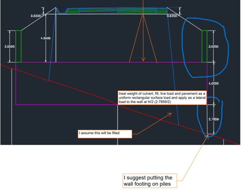
Sorry for not elaborating .Yes the purple one is a culvert ,the green ones are head wall. the white one with 2.7859 is the retaining wall I am talking about. The red line is the mountain slope and blue line is the road level. So we have a scenario where the road (blue line)together with fill is on top of a culvert (0.62+4.5606).This soil is supported by concrete head wall(green ones ,3m) .Now we have a 6X6(max, different at different location)culvert. The culvert is in half fill and half cut portion. The retaining wall (white ,2.7859m is supporting the whole thing).What I wanted to ask in OP was the surcharge load . What do you think our surcharge load looks like , the load of culvert (top and bottom slab, probably side slab too), The fill on it together with road , The live load, head wall load and the weight of water in it(fully or partially as it is not stagnated water)?
 
From the configuration, the culverts most likely operate under inlet control. I'd be surprised if they flow full. Assuming sg=2 for soil, 2.5 for concrete box, and 0.75 for the partially full culvert, the culvert load is probably not more than that of the backfill on either side of it, unless, hmmm.

Bridgebuster and BridgeSmith, would you assume the culvert would bear on more the wall than the fill, in case of poor compaction and benching, etc.?


My glass has a v/c ratio of 0.5

Maybe the tyranny of Murphy is the penalty for hubris. -
 
A few thoughts on your general design approach. I've never seen a retaining wall supporting a culvert at the outlet. It's generally not good practice. You have a zone directly below the culvert that's prone to scour especially with a 2.7m outfall. Judging from the slope and the size of the culvert, the flows are likely high and velocities significant, so flow hydraulics and scour protection (riprap design or other means) is critical. I suggest a rock (riprap apron) rather than a retaining wall.

I would also suggest placing a culvert on a slope (no more than 5% typically). This will reduce the height of the outfall at the outlet and save money on riprap aprons or reduce the size of the retaining wall.
 
Usman - some thoughts on the surcharge loading. I agree with the suggestions by AS-PEng. It's a unusual design. I strongly suggest placing the wall on piles.

ACtrafficengr - Good point about poor compaction. For stability design I would neglect the culvert loading directly on the wall stem and just treat it as a lateral load, to be on the conservative side. For structural design of the wall, some of the culvert and backfill weight would have to be included. Maybe think of the culvert as a slab with a non-uniform modulus of subgrade reaction. The higher pressure at the edge of the slab would be the load applied to the wall stem.

Picture1_hfijcw.png
 
Thankyou for your responses and time. AS Peng. I know it seems odd at first sight however we have provided Gabion blocks on the right side of said retaining wall, scouring is not an issue there ,I can increase the slope however that would increase the fill on the culvert. At some locations it will work ,at some it will not. ACtrafficeng, I went ahead with bridgebuster way where I ignored the weight of water .The culvert is already on a slope and after consulting a hydrologist they too were of the opinion that weight of water should be ignored or you will design it as a storage tank. In culverts too the weight of water on bottom slab is usually cancelled out. Bridge buster can you confirm that weight of water can be ignored ,as you have not included that in an otherwise well explained answer. Bridgebuster, Should I still put the wall footing on piles even though all stability and strength checks are ok .Its an unusual design but what you guys would had done if faced with similar problem . What you think is the better way of doing it? lastly i treated the loads as you mentioned. In addition I also included line load of side slab of culvert on stem of wall and distributed the head wall load on the surcharge.
 
Faced with the same situation, on one occasion we followed the slope with a corrugated steel structural plate pipe to reduce the velocity and used grouted riprap (large rocks grouted with lean concrete) at the outlet. On another occasion, we created a drop structure within the culvert, by dropping the bottom slab (10' x 10' box at the inlet changing to a 10' wide x 15' tall box in the middle). We used large riprap at the outlet of the drop structure also.

Rod Smith, P.E., The artist formerly known as HotRod10
 
Usman Tanveer said:
Its an unusual design but what you guys would had done if faced with similar problem . What you think is the better way of doing it?

I know that culverts and short-span bridges have different advantages / disadvantages.

What are the reasons for using a culvert instead of a driven pile supported short-span bridge?

Especially if the culvert's retaining wall is designed to be supported by driven piling anyway... per Bridgebuster's recommendation (which I agree with).

 
Bridge Smith, What is the advantage of dropping the bottom slab at the middle?? Other than reducing the velocity. Does it help the retaining wall in question in any way. SideRuleEra, Economic consideration forced us to choose a box culvert and we will only provide micro piles in areas where bearing capacity is low . Its a hilly terrain with an average bearing capacity of 3 ton psf.
 
Bridge Smith, What is the advantage of dropping the bottom slab at the middle?? Other than reducing the velocity. Does it help the retaining wall in question in any way.

It eliminates the retaining wall. You drop the outlet of the culvert down to grade at the outlet. The advantage is that much of the energy is dissipated within the concrete box.

If the options for erosion protection at the outlet are limited, you can even drop the bottom slab below the outlet to create a pool, and/or install bulkheads or baffles within the box, to further reduce the velocity at the outlet. Those measures are beyond my expertise to design, though. We have hydraulics specialists who do that type of work in our office.

Rod Smith, P.E., The artist formerly known as HotRod10
 
Status
Not open for further replies.

Part and Inventory Search

Sponsor