Eng-Tips is the largest engineering community on the Internet

Intelligent Work Forums for Engineering Professionals

Retaining Wall Multiple Loading Conditions

Status
Not open for further replies.

jreit

Structural
May 2, 2014
95
0
0
US
I have a retaining wall with some unique loading and constraints and I'm unsure of the best approach forward.
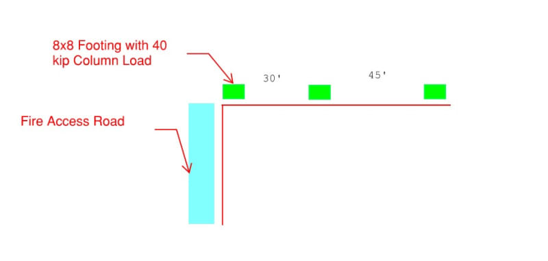
One side has a fire truck access road 1' beyond the edge of the wall. For this, I used a 250 psf surcharge (2' soil depth) as per AASHTO.
The other side has 3 columns carrying 50 kips on 8x8 spread footings spaced ~30' and 45' apart. The footings are right next to the wall.
I used the bearing pressure under each foundation which comes out to a 50/(8x8) = 780 psf surcharge to design that wall section but not sure if that's too conservative.
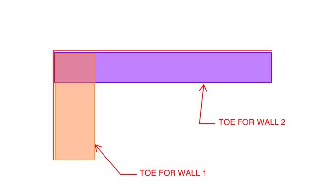
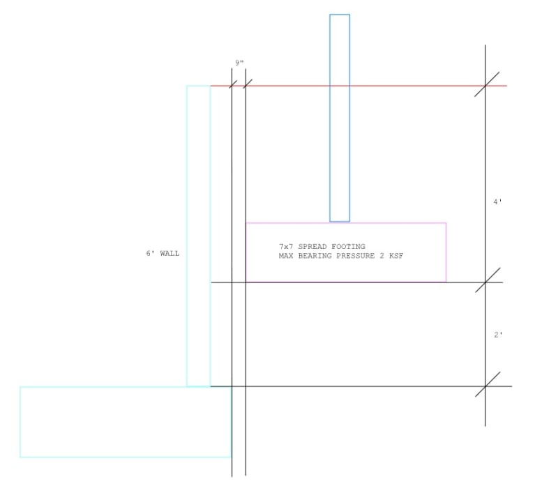
The wall is ~5' high, and can only accommodate a small heel due to geometric constraints which results in a large toe and thick foundation.
Sliding is the main issue and I'm seeing a difference in opinion as to how effective a shear key would be.

Retaining_Wall_Sketch_geawej.jpg
 
Replies continue below

Recommended for you

If sliding is the primary issue, then I would consider placing a grid of grade beams on the low side .

You could create a grid of grade beams. For example, they might be 8' o.c. and be 36" wide and 16" thick, each. Each might could be oriented perpendicular to the footing of the retaining wall. Since you have a 90 degree turn in the wall, the grade beams would intersect each other, creating a grid of grade beams. You'd have to check sliding of the system.

Alternatively, you might could use the grade beam idea, but only extend each grade beam out away from the footings by 8' or so. There, you could place a continuous concrete "dead man" that parallels the footings for the wall. This would create a place that the grade beams could "push" on.

I agree that a shear lug is probably not a good option.

Or, if you wanted to, you could integrate a soil nail system into the retaining wall.

Those are my initial thoughts.
 
Thanks for replying marinaman.
I was able to refine the design loading and get the sliding to work.
I had a question about how to best analyze the footing.
For instance, if I have a 12' toe for both walls, they will intersect.
How do I account for that?

Retaining_Wall_Sketch_2_medbld.jpg
 
For the intersection, analyze them separately. That's the conservative way. Technically, the perpendicular wall is bracing the other wall, so it more resembles a stiffened retaining wall at that side (I forgot the exact term, but it's like a retaining wall with concrete stiffener plates). I just ignore that effect because it's annoying to calculate. If you're worried about load doubling or a von-mises type of effect at that corner, it's not a concern because of that stiffening effect, and I don't think it would happen anyway.
 
Yes, thanks milkshakelake I was concerned about load doubling at the corner.

If the wall is stiffened, should I be using the at-rest pressure for design? The large wall is ~70" and the perpendicular "stiffening" wall is ~20' so I don't think the wall as a whole is stiffened, but maybe the corner is stiffened enough that it should be designed for that?
I also wanted to know the best way to analyze the effect of the column spread footing.
I am using the maximum footing bearing pressure and treating it as an infinite surcharge load (q).
I then convert that surcharge to a horizontal rectangular pressure along the height of the wall (H) with magnitude q x Ka x H.
Is that conservative or should I be using one of the alternate methods such as Boussinesq?
I am not including the vertical effect of that surcharge in my analysis.

Retaining_Wall_Sketch_3_uuy7dg.jpg
 
milkshakelake said:
Technically, the perpendicular wall is bracing the other wall, so it more resembles a stiffened retaining wall at that side (I forgot the exact term, but it's like a retaining wall with concrete stiffener plates).

That would commonly be known as a buttressed wall, at least that's what we in the DOT sphere would call it.

jreit said:
If the wall is stiffened, should I be using the at-rest pressure for design? The large wall is ~70" and the perpendicular "stiffening" wall is ~20' so I don't think the wall as a whole is stiffened, but maybe the corner is stiffened enough that it should be designed for that?

For the structural design, I would definitely consider the at-rest pressure.

I would be strongly considering a tied-back, or MSE wall for this situation. That would eliminate the need for the toe altogether. Per AASHTO, the minimum MSE reinforcement width for the side supporting the roadway would be 8', but eliminating the toe should save enough to still reduce the overall cost.
 
@BridgeSmith Thanks, that's the term I was looking for. Never actually designed one, saw it in a textbook like a decade ago.

If there's a footing right next to it, I generally use the 3D Boussinesq formulas. Though they lead to unconservative results compared to other methods. I generally use a high Poisson's ratio, much higher than is realistic, to get it in line with other methods. I think CALDOT has a pretty conservative method; I think they set Poisson's ratio to 1.0 but didn't explain it.

But the best way is to just put the footing at the bottom of the retaining wall to avoid the surcharge, or to raise the retaining wall at that level. I understand it might not be viable architecturally; it's just an ideal way to do it.

With a footing so close to your retaining wall footing, you do need to consider the vertical effect of the surcharge. To avoid messy calculations, you can just add 2000 psf to your retaining wall footing.
 
Status
Not open for further replies.
Back
Top