Cjpwdesign
Structural
- Nov 21, 2020
- 5
Dear All
Got a comprehensive redesign job for a residential extension onsite at present. The Client had a lot of difficulties with the previous Architect's and Structural Engineers. Neither bothered in coming down to site to oversee the works etc.
Essentially this all came about for me as the Client wishes to build the boundary retaining wall from reinforced masonry to make it easier and faster to build on site, as the wall stem transitions into a standard cavity wall above the external ground level. The surrounding site is only farmers fields. The ground slope from rear to front of the extension from about 2m down to 0 over a 7m length.
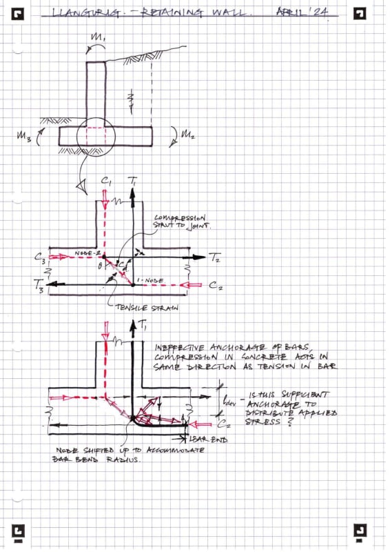
The rc concrete base and starter reinforcement bars have already been cast as per the engineers sketch attached. The first glaring error is the L-bars are backwards. I did raise this concern with the Client however he doesn't want to spend the money ripping up what has already been done.
I have reworked the design to reduce the overall stem height to maximum 2m, which should allow me to use a reduced anchorage length for the starter bars (intuitively taking into account a reduced efficiency in the opening stem/base joint).
I also proposed an upper tiered reinforced masonry retaining wall to deal with the remaining height of earth. The upper tiered wall will be treated as a separate structure with a shear key in the base to resist sliding therefore not having it's base propped by the head of the retaining wall under.
Given the current starter bar config, a strut-tie model would use a C-T-T node at the L-bar turn into the base reinforcement, putting the Lbar longer leg into tension and the shorter leg in compression. Would anyone like to hazard how thid analysis would even work?
I am concerned with brittle fracture of the concrete (even with the reduce stem height) due to the opening up of the junction between stem and base.
The previous engineers calcs for the wall are a bit of a mess, even using Tedds software, as some of the assumptions were wrong and i get a tad apoplectic everytime I look at them. (I have redesigned the entire extension as so much was just left out, like 2m roof overhangs, wall movement joints, balcony beams under torsional loading etc. etc!)
All thoughts are greatly appreciated.
Many thanks, Chris

