Eng-Tips is the largest engineering community on the Internet

Intelligent Work Forums for Engineering Professionals

  • Congratulations waross on being selected by the Tek-Tips community for having the most helpful posts in the forums last week. Way to Go!

Retaining wall to retain liquid 5

Status
Not open for further replies.

precast78

Structural
Aug 12, 2013
82
0
0
US
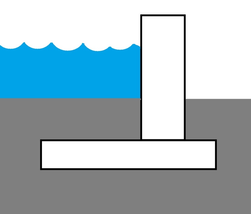
At first when I did the overturning calculation and the sliding calculation, I added the weight of the water above the heel like if I was designing it to retain soil. But the more I think about it, I feel like I should not. If I do not add the weight of the water, it seems impossible to do this. Basically we want to build a secondary containment at a chemical plant. We want to build a wall around a large tank to make sure we can contain the largest tank if it breaks. Do you think I can use the weight of water above the heel?
 
Replies continue below

Recommended for you

You are designing a tank, not a retaining wall retaining liquid (a retaining wall cannot retain liquid). As such, whether your tank is full or empty it will not slide or overturn due to the liquid. The lateral pressure due to the liquid acts in equal and opposite directions on each side of the tank. Draw a free body diagram and you will see what I mean.

Overturning and sliding results from wind or seismic forces, you will need to check cases for a full tank and an empty tank.

The secondary containment "tanks" I have seen typically have knee walls (relatively short walls, say 3' or 4' high) that are designed to contain the volume of the largest tank in addition to some allowance for rain water (say 10% of the tank volume). If this is your case, sliding or overturning of the secondary containment tank is not a problem.
 
MotorCity said:
The lateral pressure due to the liquid acts in equal and opposite directions on each side of the tank. Draw a free body diagram and you will see what I mean.
That only works if the two opposite "walls" of the tank/retaining wall are linked together right?

I think what precast78 is talking about is a perimeter retaining wall that encircles some separate tank that, if it spills, will help retain the liquid. Thus, the retaining wall is serving as an isolated, cantilevered stem wall on grade, totally unlike a tank...with not continuous base across the enclosed area. [blue](Is that correct precast78?)[/blue]

To answer the original question - I would say that you shouldn't rely on the liquid as some sort of vertical dead weight helping to hold down the heel of the retaining wall as liquids have no internal shear resistance. The liquid would simply move out of the way if the heel were to rise upward.

Check out Eng-Tips Forum's Policies here:
faq731-376
 
Yes, exactly what JAE said. It seems impossible to make it work with a precast. The liquid can go as high as 10 ft. I have to make the precast so big if I can't use the vertical load from water. The only way I can see we can do it is if they put soil on the other side almost all the way to the top of the wall. But they told us no soil on the other side.
 
I feel that it would be reasonable to include the stabilizing benefits of the water weight. After all, the water is the the source of the load. So if it's not kicking around to be used as resistance, then it's also not present to cause the demand in the first place.

I like to debate structural engineering theory -- a lot. If I challenge you on something, know that I'm doing so because I respect your opinion enough to either change it or adopt it.

In my response, I'm assuming:

1) no dirt on the heel side and;
2) moderate pace of leakage. If the water's coming in tsunami style, that's another matter.
 
I'm at a loss as to why we aren't including the water as a resisting load. Caveat being that appropriate load factors are used (ie the pressure causing overturning is factored as a load, the weight preventing overturning is factored as a resistance). A sketch might help.
 
I'm visualizing something like this. And water and soil directly over the footing would be included in the uplift resistance in that case.
This is also assumed in the foundation design for the tank, by the way.
RetainingWall_ge8ns6.jpg
 
You have to consider all possible loading conditions in the design.

I think you should look at the situations with, and without, the water, and design for the worst case.

Mike McCann, PE, SE (WA)


I'm envisioning the upside-down "T" shaped retaining structure rotating about its toe due to the overturning of the water horizontal force.

If so, the heel of the retaining wall has weight on it from water, but once it rotates only a bit, you now have water under the heel too - thus a buoyant condition for your heel with the same pressure on both sides.
The water won't push down on the heel any more that the water below it pushes up (same water pressure at the same depth).

Think of a slab of concrete underwater. The only thing pushing down on it is the buoyant weight of the slab - not the water above it since there is similar water below it.

The water will simply flow out of the way of the heel which moves upward through the water.

Now if the heel had soil above it, that soil is interconnected to the surrounding soil with an internal shear stiffness/resistance. I think there's a big difference here between heel soil and heel water.

The sketch above by JStephen does show some soil on the back side. If there is full fluid coming to the wall above this soil, then conceivably that heel soil might become fully saturated and be a dead weight on the heel to some extent.

We've debated here in the past about how much soil can be counted on over tank footing extensions to counteract buoyancy uplift. The concern of taking a wedge of soil instead of only the soil directly above the footing extension is that the soil, being saturated, may become "mush" - i.e. the soil has lost its internal shear stiffness and only the soil directly above the lip will resist uplift.


Check out Eng-Tips Forum's Policies here:
faq731-376
 
I'm not well versed in this kind of work. With these secondary containment systems, is the fluid not also "contained" from leaking into the ground? Or is is common to assume that system may fail as well? If the fluid can get under the footing then I'm also "on side" with JAE's position.

I like to debate structural engineering theory -- a lot. If I challenge you on something, know that I'm doing so because I respect your opinion enough to either change it or adopt it.
 
Ideally there is no seepage going under the foundation, but that is not real life. With seepage, you lose that benefit from above and seepage lifts.
 
@JAE: thanks for setting me straight on this.

I like to debate structural engineering theory -- a lot. If I challenge you on something, know that I'm doing so because I respect your opinion enough to either change it or adopt it.
 
If we are assuming that water finds its way below the foundation, then the coefficient of sliding friction goes way down. Its almost like a car's tires hydroplaning on a patch of wet pavement. Also, as the water seeps below the foundation, the driving force behind the wall decreases since the water level decreases due to the seepage.
 
I had a similar project in the past. I also struggled with using the dead load of the water. I recommended concrete sheet pile wall but another option would be to use helical piers or auger cast piles on the tension side of the footing. It's definitely more expensive.
 
I agree that unless you introduce soil and then a liner above it on the inside of the wall, with your upside down tee, then the basic answer to the original question is no.

Of course you could do that with something like the sketch by J Stephen or simply lay it on the ground and back fill from beyond the heel / T to the top of the wall at a suitable angle to provide your static load.

~This would also reduce any shock loading from a wall of liquid racing to ward the wall from a catastrophic collapse. It reduces the bund volume, but only by a small amount.

This is bund wall design of which there are many examples.

As said a few times, a sketch of what you're thinking about / options would help.

Remember - More details = better answers
Also: If you get a response it's polite to respond to it.
 
LittleInch, JStephen's sketch is accurate except the client wanted the precast piece sitting at grade (not possible). So I am proposing what JStephen sketched. It will be buried 6 to 7 ft.
 
Status
Not open for further replies.
Back
Top