Continue to Site

Eng-Tips is the largest engineering community on the Internet

Intelligent Work Forums for Engineering Professionals

  • Congratulations waross on being selected by the Eng-Tips community for having the most helpful posts in the forums last week. Way to Go!

Retaining wall toe design 1

Status
Not open for further replies.

wrxsti

Structural
Sep 18, 2020
196
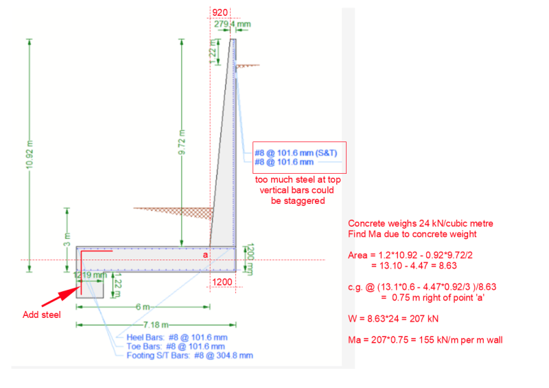
I was perusing a particular retaining wall design example

For the design moment for the toe at the stem
if the pressure on the toe creates a larger moment
than the moment in the stem
the max moment for the stem overrides the larger moment for the
toe using the pressure

 
Replies continue below

Recommended for you

Maximum factored moment at point 'a' is required. Factors 1.2 for dead load and 1.6 for active pressure are being used which seems conservative, but that's okay. I am not familiar with your code.

1.2D + 1.6H = 1.2*155 - 1.6*5.24(8.5+0.6)[sup]3[/sup]/6 = 186 - 1053 = -867kN-m (CCW moment).
The maximum factored stem moment is 1.6*5.24(8.5)[sup]3[/sup]/6 = -858kN-m

Unless I have made a mistake (a high probability), the net factored moment is 867kN-m at point 'a' on the neutral axis of the footing. This is nearly identical to Mu[stem].

I have not checked the amount of reinforcement, but #8@101.6mm seems excessive in the upper part of the wall. The downturned concrete at the end of the toe will resist passive pressure and should have additional steel as shown (if necessary, hooked at the bottom).

Using Imperial bar numbers with metric spacing is not recommended as it could be misinterpreted. I assume #8@101.6mm is intended to be #8 @ 4". All dimensions are metric, so probably it would be better to specify 25M@100 (101.6 is not easy to measure, using a metric tape)

image_w9jhaz.png


EDIT: If there is upward soil pressure on the footing to the right of Point 'a', that would increase the CCW moment. I did not consider it, but suspect it is there. In any event, it is not very significant.

BA
 
If this wall is in a modest to high seismic region, I'll go one step beyond BA's suggestion. Reinforce the turndown as a torsional element - provide longitudinal bars enclosed in stirrups. The wall will move back-forth in both directions, so either face will subjects to tension at a time. The damage there is difficult to discover and repair, so be a little conservative.
 
Yes the drawing is not the actual full reinforcement drawing there will be bars in the key for sure i hope

@BARetired ok so your calculation with the stem weight moment about a
is now reducing the 1000 from your earlier calculation to 800
which is more towards the stem moment...

so the design for 1000 is not warranted?


jsmith234 said:
so the design for 1000 is not warranted?

It appears to be the case, so far as I can see, although I have not calculated the soil pressure under the wall which would tend to increase the footing moment.

Probably the more critical part of the analysis is how to reinforce for a specified moment around a 90 degree corner. This case is different than the usual retaining wall footing where there is a heel as well as a toe. In that case, bars can be extended beyond the point where they are required and diagonal bars can be added across the re-entrant corner. #8 bars require a sizable radius of bend and the bearing stress of the bars around the bend has to be considered if the stem reinforcement is simply being bent into the bottom of the footing.

Mechanical anchorage may be a better option for the tension reinforcement in the retaining wall and footing to avoid the large radius curve.


BA
 
@BAretired i agree that reinforcement detail doesn't show the length of the stem reinforcement into the toe
Also there can be no diagonal bar to help with the cracking at the tension face of the wall meeting the footing

Worse issues when there is no toe either, heh
do you have any detailing recommendations for no toe or no heel walls?
 
Can't recall ever designing a retaining wall with no toe or no heel. They are both corner details. With no toe, the right angle is tending to open, but diagonal bars can be added at the re-entrant angle. With no heel, the angle is trying to close with no possibility of adding a diagonal bar.

One way to look at it is by using the strut and tie model. I have never used it on an actual project, so I probably should keep quiet, but I believe it could be an effective tool for solving this type of problem.

My current feeling is that in the absence of either toe or heel, the vertical tension bars in the wall and the horizontal tension bars in the footing should terminate at the junction with a mechanical anchor, but I'd be interested to hear what others think on the subject.

EDIT: If the footing has a key (turned down portion) to create more passive pressure and if the key is located such that the vertical wall bars can be fully developed, mechanical anchorage would not be necessary for the wall, but would be for the footing.

BA
 
Yea in one of the threads a guy recommends adding even a foot of toe
but it is also recommended that after the stem bar bends into the toe, there is enough horizontal
length to lap with the toe horizontal.
This can not happen in 1ft so im not sure if there is increased efficiency adding 1ft toe
to turn into the toe versus turning back into the heel.
 
or possibly design to the efficiency of whatever detail chosen
 
jsmith234 said:
This can not happen in 1ft so im not sure if there is increased efficiency adding 1ft toe
to turn into the toe versus turning back into the heel.

If anchorage is all that is required of the vertical bar, it is not clear why the direction matters. A one foot long toe does not have much moment, so doesn't need much, if any, steel reinforcement. In this case, it seems that any direction is as good as any other. Some say otherwise, but to me, it's not clear why.

BA
 
i think its for the tension stresses travelling around the bend to be resisted by the resultant compressive force
formed by the outside of the wall and the top of the toe meeting at the joint

as well as not having to loop the bar
amongst other factors

have you experience in looping bars ?

maybe using U bars for each side and have a diagonal?
 
Too many unknowns with regard to a retaining wall this high. A new question has just surfaced in thread507-474137; does active pressure exist on the back of the shear key. This affects the stability of the entire wall. Needs careful study and probably some input from geotechs.

BA
 
jsmith234 its the bond forces from the reinforcement should be resisted by another compressive strut
 
Status
Not open for further replies.

Part and Inventory Search

Sponsor