SSKKND
Geotechnical
- Apr 14, 2003
- 3
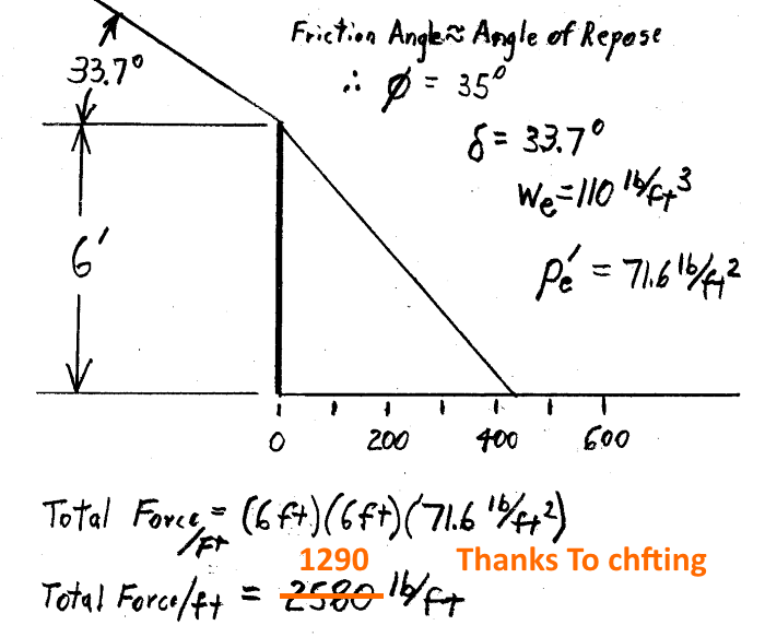
Hi sifu. I have questions and require expertise inputs in regarding the geotechnical’s analysis approaches for a retaining wall with inclined backfills. The reasons are that I saw hand calculations that are different from what I normally read in Das or Bowles text book. The hand calculations (which i was told was based on older test book) appear to present lower forces acting against the retaining wall
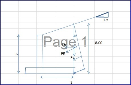
I would like to discuss and check whether these alternative approaches are correct or not. I have attached the sketches for better understanding.
For simplification, let’s assume the inclined slope is infinity, no hydrostatic pressure acting against the wall, the backfills and the existing soils are of the same cohesionless soils, and all the extent and sizes are in the attached sketches. I hope that’s’ more than enough info.
Approach 1
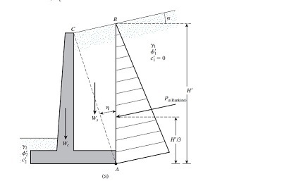
The approach 1 is typical textbook formula. Calculate Ka based on the incline slope, friction angle of backfills, wall-soil friction, etc, and derive with a resultant force acting parallel with the inclined slope. The forces acting against the wall are basically the resultant forces time the cos (inclined slope angle).
Approach 2
The approach 2 is to draw a line in 1:1 from the heel and intersect with the horizontal line from the top of wall (at point 0). Then treat the inclined backfills within the triangle area (ABO) as surcharge, and then redistribute them as an equivalent uniform surcharge load along line AO. Since the triangle area (AB0) was treated as surcharge, then the backfills beneath the triangle was treated as normal active pressure. Thus, Ka (excluding the inclined slope factor) was much smaller than the approach 1. Subsequent analyses of forces acting horizontal against the walls were calculated.
Approach 3
The approach 3 is similar to approach 2 but with exception that line from heel shall intersect with inclined slope. Then treat the inclined backfills within the triangle area (ACO) as surcharge, and then redistribute them as an equivalent uniform surcharge load along line AD.
The approach 2 and 3 provide identical results but almost ½ smaller than approach 1.
Any ideas?![[ponder] [ponder] [ponder]](/data/assets/smilies/ponder.gif)
![[ponder] [ponder] [ponder]](/data/assets/smilies/ponder.gif)
I would like to discuss and check whether these alternative approaches are correct or not. I have attached the sketches for better understanding.
For simplification, let’s assume the inclined slope is infinity, no hydrostatic pressure acting against the wall, the backfills and the existing soils are of the same cohesionless soils, and all the extent and sizes are in the attached sketches. I hope that’s’ more than enough info.
Approach 1
The approach 1 is typical textbook formula. Calculate Ka based on the incline slope, friction angle of backfills, wall-soil friction, etc, and derive with a resultant force acting parallel with the inclined slope. The forces acting against the wall are basically the resultant forces time the cos (inclined slope angle).
Approach 2
The approach 2 is to draw a line in 1:1 from the heel and intersect with the horizontal line from the top of wall (at point 0). Then treat the inclined backfills within the triangle area (ABO) as surcharge, and then redistribute them as an equivalent uniform surcharge load along line AO. Since the triangle area (AB0) was treated as surcharge, then the backfills beneath the triangle was treated as normal active pressure. Thus, Ka (excluding the inclined slope factor) was much smaller than the approach 1. Subsequent analyses of forces acting horizontal against the walls were calculated.
Approach 3
The approach 3 is similar to approach 2 but with exception that line from heel shall intersect with inclined slope. Then treat the inclined backfills within the triangle area (ACO) as surcharge, and then redistribute them as an equivalent uniform surcharge load along line AD.
The approach 2 and 3 provide identical results but almost ½ smaller than approach 1.
Any ideas?
![[ponder] [ponder] [ponder]](/data/assets/smilies/ponder.gif)
![[ponder] [ponder] [ponder]](/data/assets/smilies/ponder.gif)

![[idea] [idea] [idea]](/data/assets/smilies/idea.gif)
![[r2d2] [r2d2] [r2d2]](/data/assets/smilies/r2d2.gif)
![[bigsmile] [bigsmile] [bigsmile]](/data/assets/smilies/bigsmile.gif) , that’s what I have in mind. The "approach 2" and "approach 3" follows the principles of the hand calculations that have been shown to me (which i should mentioned in my earlier post that are different from what I normally do). These principles are provided by seniors who are saying coulomb or rankine are too conservative when with deep slope. And 45 degree from heel is a conservative line for a rupture surface or active wedges. Of course, to be really exact, may need to do a cullmann’s graphical method to determine it. But that will be another story….
, that’s what I have in mind. The "approach 2" and "approach 3" follows the principles of the hand calculations that have been shown to me (which i should mentioned in my earlier post that are different from what I normally do). These principles are provided by seniors who are saying coulomb or rankine are too conservative when with deep slope. And 45 degree from heel is a conservative line for a rupture surface or active wedges. Of course, to be really exact, may need to do a cullmann’s graphical method to determine it. But that will be another story….![[smile] [smile] [smile]](/data/assets/smilies/smile.gif)
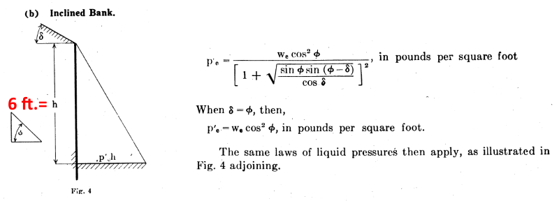
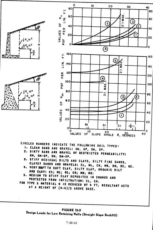
![[surprise] [surprise] [surprise]](/data/assets/smilies/surprise.gif) . hmmm....maybe these analysis approaches 2 and 3 are not that unorthodox at all. OldestGuy. Have u seen the analysis approach 2 and 3 before?
. hmmm....maybe these analysis approaches 2 and 3 are not that unorthodox at all. OldestGuy. Have u seen the analysis approach 2 and 3 before?