Continue to Site

Eng-Tips is the largest engineering community on the Internet

Intelligent Work Forums for Engineering Professionals

  • Congratulations KootK on being selected by the Eng-Tips community for having the most helpful posts in the forums last week. Way to Go!

Retention tank uplift (buoyancy) 1

Status
Not open for further replies.

Eng.nmarko

Structural
Jul 29, 2019
9
Hi guys,

I'm having a storm water retention tank which is 4.85 m deep in the ground, it is in a flood area, therefore ground water is considered full depth of the tank, base is about 51x21 m.
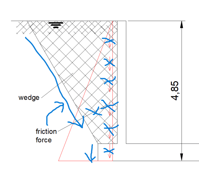
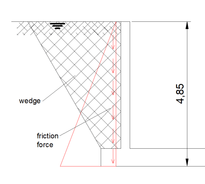
It is open, no top slab, as a pool. Bottom slab is 0.6 m deep, walls are 0.3 m. My question is if I use a bottom slab overhangs, is it correct to activate ground as a wedge and use the wedge weight against the uplift force. Also what is the cohesion force for saturated soil, I would use it as a friction force for stabilizing force as well. See attached picture for the reference.
2023-10-17_13_53_01-GstarCAD_2022_Professional_-_Drawing1.dwg_khmif6.png


Many thanks,

Marko
 
Replies continue below

Recommended for you

I have been taught to ignore the soil wedge of saturated soil and only use the soil directly over my footing extension in this exact situation. This is a mix of saturated soil is much weaker, this is also relying compacted fill interlocking rigidly after potentially only a few years, and it is just an increased factor of safety while not being all that unconservative.
 
WesternJeb, thanks for this, and what about the friction forces, did you consider it?
 
The soil would be acting as a gravity load (saturated weight minus the weight of water) on top of your footing. You will just have a rectangular section without forming the soil wedge.

If this is the case, I don't believe you will have a need to activate any friction force in the vertical direction, it is just soil bearing on top of your footing and applying a gravity load that would help resist overturning. Sliding (friction in the horizontal direction) isn't an issue since the base of your wall is integral with a concrete slab on the bottom of your tank.
 
About the weight of the soil which is acting on top of the footing, in calculations I'm using uplift force as:
H x B x L x gama(w), where
H - depth measured from the level of ground water to the bottom of founds,
B - foundation width
L - foundation length
gama(w) - water specific weight ~10kN/m3

In this case I think if I reduce the weight (saturated soil) acting on top of the foundation, seems I'm doing it twice, as it is already included in the formula above?

The tank is as you said integral, so no problem in terms of overturning and sliding, it is basically a pool.

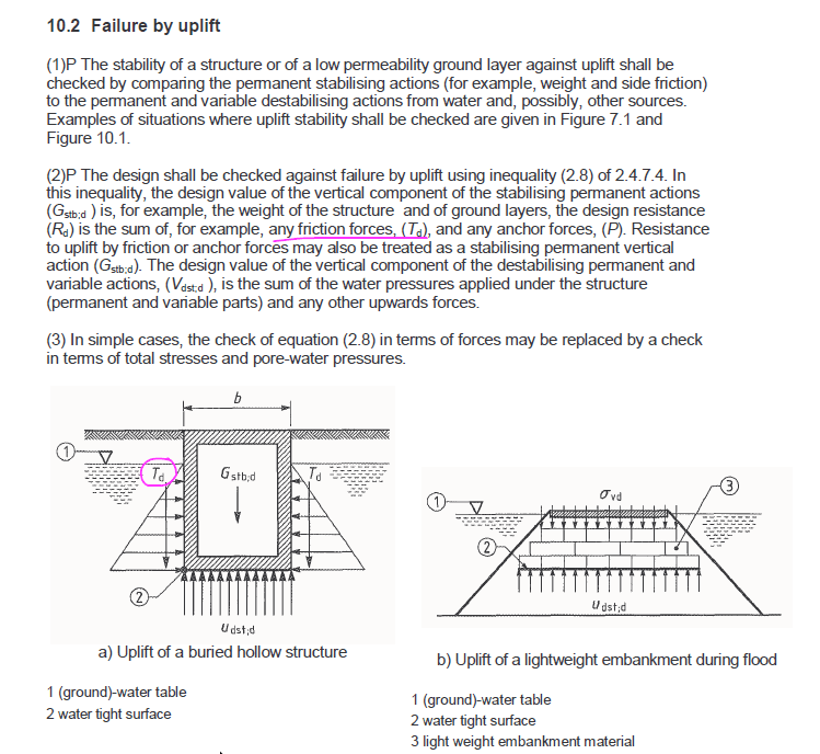
The question is what is the friction force between the tank wall and the soil, it is growing with the depth of the soil, lineary due to active pressure etc. See attached picture.

2023-10-17_15_26_24-BS-EN1997-1_E_2004.pdf_-_Adobe_Acrobat_Reader_64-bit_l1gitf.png
 
The snippet you have sent through is not the same situation as what you have. You have a footing extension.

Friction would resist the tank rising up if it didn't have a footing extension, but it wouldn't be anywhere near the full weight of the soil.

Think about how YOUR structure would fail with a footing extension. In order to come out of the ground, the soil on top of the footing extension would have to come with it. It would be gravity bearing, there wouldn't be any additional friction force between the soil and side of your wall providing extra capacity. I see your thought process, I am just letting you know what my senior engineers have taught me. It is a design simplification, and especially with everything being saturated.
 
Yes, that is all correct, had no senior engineers here to give me valuable advice on this topics so thank you for sharing this with me.

Sounds fair saying there is no friction in case of extended foundation (except along the thickness of the foundation), however the failure surface is going to be somewhere else and seems neglecting that impact might be too conservative, I believe this can be included, seems this is about shear strength of the soil, this article looks promising However, I would go with safer variant, as you proposed, unless I have firm evidence about considering uplift soil resistance.
 
I take the shear failure plane vertical from the edge of my extended footing and directly upward, no soil wedge. Sometimes it is worth sharpening your pencil if you are getting absolutely ridiculous results from it.

You also need to check your base slab for the upward bending moment due to the buoyancy force acting on the bottom of your slab. That has caught me off guard a few times with how much concrete and reinforcement is required due to that bending moment, usually because the base slab is has relatively long spans.
 
Boy this takes me back. I haven't done one of these in quite some time (circa 2000, well, maybe a little in 2005 but that was for a golf course and I don't think it ever went live, plus it was this goofy multi-cellular tank, not awesome).

The friction along the length of the failure surface, I'd say, is typically neglected. It's also a friction force so there's special treatment in the ASCE code, and it's also inclined along the presumed failure angle, so it's not fully downward.

Second - the "passive uplift resistance" you're looking for the volume of a frustrum, times the soil unit weight. I have that somewhere but it's odd. Area at top, area at bottom and 4x area at mid height(?) times some dimensions. (this is the wrong frustrum but you get the idea)

This one, maybe.

The soil doesn't come out "straight up" but if you'd like, run it both ways and see how you feel. With a cohesionless soil (sand), you'd perhaps get the "straight up" soil case. I don't agree you are relying on compaction here. Soil has density, if it's compacted, the density is higher. Use the values that are intended from the 95% proctor compaction or whatever is being specified.

If you want a "normal people see this happen" you are looking for swimming pool uplift, or "popping out of the ground" seems to be the more common term, when the pool isn't filled due to high water table, (these things are "normally" done in shotcrete so they won't have the footing extension a WTP or WWTP will have (to develop the bars, to prevent catastrophic failure during a "water test", when empty and backfilled, etc.). They also have thinner cross sections (4"?) so they are more prone to "uplift."

Degenkolb can't spell buoyancy correctly, but here's their write up, use at your own risk.

If there's a flood at least some of the soil might be considered saturated, floods depend on either a) rainfall exceeding the infiltration rate (so the soil below is saturated somewhat but need not be not full depth), this produces runoff, probably Hortonian overland flow, in the stricter sense), or b) saturated soil full depth due to some kind of apocalyptic "it rained for 5 days straight" monsoon season sort of thing. Or the more obvious river flooding/ storm surge/ etc.

(so the resisting soil weight is thus net weight (at least partly) to resist uplift, not gross) but I believe it's more commonly presumed to be full depth, possibly due to a lack of sophistication on the part of the analyst, or a desire to be extra conservative given the consequences of failure (pipe rupture, tank moves up six inches, mat fails, boil water notice, wastewater leaks into the river and creates a boil water notice for five hundred miles downstream affecting millions, etc.

Alternately, if there is a pressure relief valve, that may change the loading). It would be abnormal for the water table to be fully saturated, a flood to occur, AND for the tank to be completely empty. It may be more commonly designed that way, but it doesn't feel like a rational load case.

Plus, if you are in a seismic zone or a flood zone, there's various standards that mandate freeboard (height of the tank wall above the base of the flood). Freeboard for a flood is to address changes in flood, level of development, sea level rise, river rise, etc, freeboard for seismic is to prevent the liquids sloshing out due to the ground motion (seiche waves?) The requirements are there for different reasons.

Regards,
Brian
 
@lexpatrie thanks for this. Not sure about the shotcrete comment, here the case is wide excavation and in-situ shuttered concrete wals, so that shouldn't be a problem.

About the tank being empty during floods is certainly questionable, I will have a look and try to find out how much water is realistic to stay in the tank during the flood as the real water table is 1.5m below ground level.

Standards regarding the required height of the tank above ground level is not my concern as a structural engineer but it is worth of mentioning.

Regarding seismic it is in seismic area and the wave design is considered in the structral design.

Many thanks,

Marko
 
The shotcrete pertains to the general phenomenon you are looking at, the tank being ejected from the ground due to hydraulic forces, what I mean there is there's no "lip" in a shotcrete pool that would capture any soil and help to keep it in the ground. They are basically a bowl of concrete, not strictly a slab extending past the vertical wall, and a wall with a waterstop between them. Given the amount of "literature" on the internet on this phenomenon, it happens, (and it doesn't happen just during flooding, high water table/saturated ground can do it, it seems). The other bit is the pool is usually away from a building on exposed ground (like a WTP/WWTP tank), rather than inside a building where the foundation might shield it from high ground water.

If you're not providing top of the tank as the Structural Engineer, who is? Are you expecting a contractor or architect to wade through the freeboard requirements?

In that first drawing, you show a soil wedge and skin friction along the side of the wall, pointing directly down. If the whole thing (tank and soil wedge) comes out of the ground, the skin friction doesn't count (it cancels out, because it's an internal force between the concrete and the soil that are both moving upward as a mechanism...). If you want to be really aggressive, there could be some skin friction/sliding resistance along the angle of the soil wedge, but it doesn't point directly down, it's along the angle of the soil wedge, and I've not seen it done. I've seen skin friction used for piles, but I've not seen it used for WTP/WWTP. Then again, I have a limited history with tanks.

I missed you said this was a stormwater retention tank, so filling it with water before a flood seems unwise, same with a PRV.

Regards,
Brian
 
@lexpatrie I asked about a specific tank as in the image shown, not in general, so I was surprised you mentioned shotcrete etc. But thank you for the additional info.

Freeboard details (level) are specified by a civil/hydrology engineer, at least in my country.

Seems you didn't read all the answers in the thread. So regarding skin friction/sliding resistance (uplift resistance of soil) it is something I already proposed and then PEinc sent a full design of uplift where American Concrete Pipe Association published an article which considers soil shear strength by using a vertical failure surface.

Why do you think it is not going to fill with water during a flood? It is taking water from 50000 m2 surface, so it should be reasaonable to assume there is water in the tank while it is a flood.

Thanks,

Marko
 
Oh I read it. You can't put a friction force between two things that are NOT MOVING relative to each other. Your soil friction arrow is in the wrong place. I haven't seen soil friction used in the buoyancy check on a tank. I've actually used the soil wedge to combat buoyancy.

2023-10-17_13_53_01-GstarCAD_2022_Professional_-_Drawing1.dwg_khmif6_xcrtpo.png


Those pipe people may use a friction force for a vertical soil column, but the friction force is between the piece of soil that is moving (with the concrete) and the soil that is not moving. This is at least in line with practice of using skin friction (but no soil column) for an uplift caisson.

You're on the hook for providing bars in the freeboard. So while the number of the elevation may not be yours, it belongs on your drawing. "We" structural engineers may not set the finished floor elevation, it still shows up on our drawings, typically. Plus, the freeboard affects your design so you need to know where the top of the tank is.

What I meant was if you had a buoyancy problem, when the tank is empty, one thing that might fix it/help is a pressure relief valve at the bottom, or filling the tank before the flood. Since it's supposed to detain (floodwater) that's not a viable option. My background here is Water treatment/Wastewater treatment (WTP/WWTP), not detention tanks, in a WWTP a PRV is perhaps tenable (the water getting into the tank is pre-treatment "polluted" water already, but a PRV in a WTP (at least post-treatment) means your water is no longer sanitary.

Tanks are sometimes "water tested" (i.e. filled completely with water without backfill to confirm it retains water adequately) and if so, that will affect design. It also gets backfilled without having water in the tank, creating another load case.

If your tank is empty until the flood goes above the freeboard, then the tank is probably empty. There should be some water level in the tank due to I suppose, rainfall, but the purpose of the tank is to accumulate water, so it should fill at some point during the flood, but when exactly affects your buoyancy calculation. If the flood elevation is reached after the tank is full, there's not much going to happen, if the tank is completely empty and the flood is at the freeboard, that will be the maximum buoyant force. Reality will be between these two extremes.
 
Friction doesn't occur only if the two solids/surfaces slide, it occurs also when two surfaces try to move (they are in balance due to the friction)
 
No. or rather, irrelevant. You can't put in an internal friction force that cancels out in the free body diagram, then add a second friction force at the interface. Or, you can put it in, but it won't be there in reality.

Customarily one does not use static friction in these situations. Static friction is higher than sliding friction, so you end up with an unsafe design. Again, I've not seen a buoyancy calculation for a tank that uses sliding friction along the soil boundary. If the soil is wet that friction force will be fairly low anyway, or zero if it's cohesionless (sand).
 
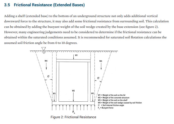
This link has a section on OP's question, with them recommending to exercise judgment when assuming friction, and to assume a wedge of 0-10 degrees.


Capture_txzlby.jpg


It's an interesting question as to what sort of wedge, if any, can develop. When calculating forces on walls with saturated backfill we still use these standard earth pressure theories with large friction angles, and corresponding failure wedges, so what's really going on? Why are the basic earth pressure theories still ok to use underwater when the soil is mush and isn't as frictional any more, and isn't wedging like that anymore?

Personally, when calculating tank and swimming pool uplift I've always just treated the soil as water, and made sure there's enough mass to hold it down, i.e. No wedging. No friction.
 
Yeah the angle (sigma in that drawing) depends on the soil properties, sand, being generally cohesionless, won't have a sigma. I also notice that there is no frictional force along the hypotenuse of the soil wedge.

Swimming pools are smaller, so it's perhaps less useful to add the wedge, when it comes to a full-on WTP/WWTP tank, it seemed common to me at the time. Not that I was sealing the design. I was the junior guy running the SAP/SAFE model, and doing the uplift (buoyancy) check. The other thing that might affect it is the old eminent domain areas where WTP/WWTP were placed were in terrible soils, putrid MSRs, etc. So using every plausible "kitchen sink" to make the buoyancy check work might be involved.

Since they aren't suing the sliding friction along the interface, perhaps that's where the conservatism enters in.
 
@lexpartie, there is no friction in sand? Just read the pipe people paper as you called it, it's based on American Standards etc.
 
Status
Not open for further replies.

Part and Inventory Search

Sponsor