Eng-Tips is the largest engineering community on the Internet

Intelligent Work Forums for Engineering Professionals

Retrofit Existing Longspan Large Ridge Beam 1

Status
Not open for further replies.

CableSCES

Structural
Jun 14, 2023
3
0
1
US
Hi everyone! This is my first post to these forums - I have been a lurker for about 15 years or so, and have learned an incredible amount from you all here. Thank you for humbly and not condescendingly sharing your knowledge and wisdom here for many like myself to learn from.

My post is a similar problem to this one that I found: But I didn't want to hijack his thread with my specific situation.

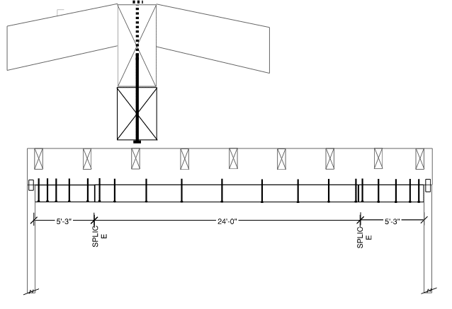
The beam I'm trying to retrofit is a 34'-6" long (E) 6x14 simple-spanned ridge beam (no tension ties, vaulted ceiling - holy moly who designed a 34' span wood beam ever). The beam is showing signs of distress and causing issues throughout the roof and home. The beam and surrounding elements creak whenever wind hits the building. When calculated for DL+LL+WL, the beam is significantly overstressed (1.95 DCR).

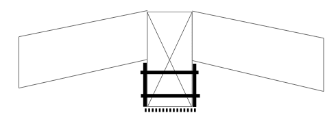
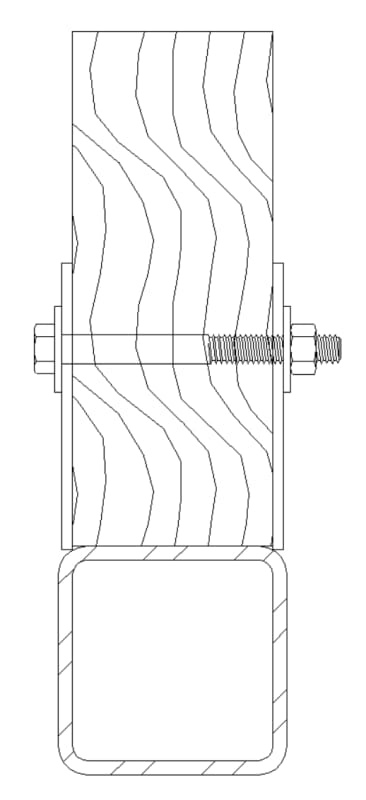
I'm wondering if I can use Dik's HSS with thru-bolt detail from that thread on my dilemma. But to clarify, is that sketch intending to be linear-add strengths, like a vertically stacked sistering, or are the bolts engaging composite action? (Hopefully @Dik will see this)

tubesteel_ridge_beam_retrofit_d4hkcw.jpg


A 6x20 works when I calc it, so my intent was to build-up a composite section. My initial thought was similar to the other thread's initial idea: Stack another 6x10 directly beneath the existing beam for the middle 24' or so (practical length of getting a new beam into the home), and lag bolt it up into the bottom of the existing beam. Trouble is, VQ/I shows me needing 3/4" lag screws @ 4" OC. This would basically decimate the continuity of tension and compression fibers in the new beam, and cut the tension fibers in the existing beam too. If the lag screws are installed through the bottom, in the center, that's removing approximately 14% (0.75in/5.5in) of the fibers. I don't think I like essentially carving a channel out of the middle of both beams. Plus installing 16" long lag screws straight up is no easy construction task.

The complexity with retrofit comes with the length of the existing - just purchasing a new wood piece 34' long would be a challenge, let alone getting it into the building. So a partial reinforcement of the length seemed prudent, then fill in the sides to make it look continuous. It's a high-value custom home with ocean view about 1mile downhill, so ofcourse the clients don't want anything unsightly in their vaulted ceiling like post-tension cables and struts.

But if I could do it out of steel like that sketch, the contractor could field splice-weld the tube steel and bracket element together into a single 34' long piece, and lift it into place.

My question @Dik for your sketch - if it is intended to make this composite, how do I calculate the force flow transfer through the thru-bolts in your sketch above? If it's just linear add EI strengths, then the bolts are just enforcing vertical compatibility transferring the uniform load down to give the tube steel its portion (similar to what's discussed here:
If you folks have any other ideas for this retrofit, I'm all ears. Thanks in advance!
 
Replies continue below

Recommended for you

Congrats on your first post here!

I'm surprised this only fails by 1.95 being that it's spanning 34'-6"

I won't try to answer any of the questions that you've addressed to Dik, but following are a few quick thoughts:
[ol 1]
[li]If the intention is to construct the tube with the tabs/plates already welded on and then lift it up into place, I'm not saying this can't work, but I think you may run into some difficulties if the existing beam has deflected any appreciable amount (which it likely has) and also if the beam isn't perfectly straight.[/li]
[li]Rather than using lag screws for shear flow transfer, you might want to use thru bolts. Per NDS, this should give you much higher capacity, thus needing less connections. Refer to the table with bolts in double shear with 1/4" steel side plates.[/li]
[li]You mention needing 3/4" lag screws @ 4" OC for shear transfer, but I assume this is only at the ends where shear is highest. Is that accurate? If so, you should only need this many fasteners at the ends. At the exact middle, where shear is theoretically zero (for a simply supported uniformly loaded beam), you shouldn't need any fasteners (at that exact location).[/li]
[li]For other ideas, I'd consider adding steel plates to the sides, although this is probably only possible if rafters are above the beam. Steel channels are another option. It sounds like that could depend too on what the owner is ok with aesthetically.[/li]
[/ol]
 
I would recommend treating the steel/wood member as non-composite. Each member would simply resist load proportional to its stiffness (EI). Any tie between the two would be for stability, uplift, and "bonus" composite action.

I am not seeing the advantage to the field splice (unless you will have problems getting the beam into the house itself) and would recommend avoiding a field splice of a bending member if possible. You may be forced to, but this may not be a simple weld (especially if the tube walls are relatively thin.) Far from impossible, but not one I would recommend if you are self-installing or have typical residential guys working on this.

Regarding the wood option, there are better fastener options than lag screws available and also the potential of adding plywood plates as suggested in the linked thread. I agree with your concerns about getting a 34' member though.

 
An HSS6 wont touch this unless it is composite. I think you will have a hard time getting enough fasteners in it to achieve that though.
Can you just put an I-beam below it?
 
Thanks for the replies already. Appreciate the brainpower and insights.

Eng16080 said:
1. you may run into some difficulties if the existing beam has deflected any appreciable amount... and also if the beam isn't perfectly straight
This is correct, my construction sequencing concept is to lift the reinforcing beam in place beneath the existing, then apply a jacking force to the underside to lift the existing beam into an unloaded condition, then place posts beneath the new double-beam periodically to push the two beams flush along full length. Once they're both straight and in full contact, drill the holes, install the fasteners, then left it back down as a combined member. The straightness is a good point - the existing beam is fairly straight when assessed in the field, I'll have to the let the contractor work out the straightness compatibility.

Eng16080 said:
2. Rather than using lag screws for shear flow transfer, you might want to use thru bolts.
You're referring to my original underside lag bolt concept? Here is a sketch of what my original concept was.
beam_lag_retrofit_sketch_fzsa3h.png

I am still worried with through bolts that I am cutting completely through the tension and compression fibers of the new beam so often, and also cutting out some of the existing tension fibers in the existing beam. You're just leaving little strips of continuous fibers along the center of the beam. I can get a 5/8" thru-bolt to work with similar capacity as a 3/4" lag-bolt, so that amounts to an 11% reduction in fiber count by drilling straight up through both beams. I guess I could just reduce the capacity of the combined-beam by 11% and make sure it still works. Minus the bump on the roof for the nut/washer which they can cover with roofing cap+goop easily, the thru-bolt is probably easier to install also.

The other concern is the "splice" locations noted. Due to constructability space constraints for getting a long beam into the house and ability to procure long wood beams, the contractor can only get a 24' beam in there. I can still add small sections to each end to make it look continuous, but short of steel strap (ugly), they're going to function separately. I'm unsure how the force distribution is different in just the middle 24' section there using q=VQ/I. I've tried to compare with similar steel detailing, but the MQ/I at the ends, I'm not sure how I transfer that out into wood at the ends of the 24' section.

Eng16080 said:
3. You mention needing 3/4" lag screws @ 4" OC for shear transfer, but I assume this is only at the ends where shear is highest. Is that accurate? If so, you should only need this many fasteners at the ends. At the exact middle, where shear is theoretically zero (for a simply supported uniformly loaded beam), you shouldn't need any fasteners (at that exact location).
Practically when I've designed composite sections in the past, I've never taken the reduction along the length, I just take the highest shear and apply that fastener spacing to the whole member. But you're right, this longspan may be one case where I use the reduced spacing along the length. I have reflected that concept in my sketch above.

Eng16080 said:
4. For other ideas, I'd consider adding steel plates to the sides, although this is probably only possible if rafters are above the beam. Steel channels are another option. It sounds like that could depend too on what the owner is ok with aesthetically.
Yes I considered something like this (dashed line along the bottom optional like a capture channel), but the complexity of the dissimilar materials with non-fullheight eccentricity was offputting:
beam_side-plate_retrofit_sketch_n86kr1.png

I could consider it like a concrete beam, compression in the top, rely on the steel for the tension along the bottom. Then it just comes down to the force transfer through the bolts to say it's acting so coherently compositely. That would just be q=VQ/I also given the eccentricity, yes?
Alternatively I could consider them to be like flitch plates, I found this thread using transformation and calculating a new NA. Same concept of compression in wood and tension in steel.
RWW0002 said:
I am not seeing the advantage to the field splice (unless you will have problems getting the beam into the house itself)
You mentioned the exact concern: getting the beam into the house. We can't practically get longer than a 24' piece in through the house. The other is ability to procure the beam. Steel will be easier for sure, but still can't twist it around inside the space enough to get it in place. Thus field splice-welding was my concept solution for constructability.

RWW0002 said:
the potential of adding plywood plates as suggested in the linked thread
I don't know why, but this plywood side-plates concept seems hokey to me. Perhaps because it won't be visually pleasing, but also I'm relying on the stitched plywood pieces to distribute all the VQ/I forces between the existing and new beam, and short of calculations it just doesn't seem strong enough for that. Perhaps I'm wrong there.

XR250 said:
Can you just put an I-beam below it?
Yes, that is an option instead of the HSS. And again just stack the EI stiffness linearly? I-beam will be unsightly, that's why I initially dismissed it. Perhaps they could put a faux beam cover over it. I'll consider the option, thank you.
 
CableSCES, By thru bolt, what I meant is to construct it like shown in the first detail at the top of this page. If that's what you meant by "lag screws," then I misunderstood. I normally call the connection per that detail a thru bolt connection, which happens to be in double shear. I didn't mean to that you should bolt through the existing beam vertically.

You may want to inform the owner that jacking up the existing beam to be straight could cause damage to the ceiling and/or the roof. I think it's unlikely (but not impossible) that the roof could leak after doing this. Just a CYA thing.

I wouldn't use the worst case fastener spacing especially considering that you're worried about the close spacing. You'll end up using twice as many fasteners (or something like that).

Ok, the steel side plate/channel idea probably doesn't make sense being that the rafters frame into the side of the beam.

I would alternatively consider adding a new wood beam below of the same material and width and using steel or plywood side plates to connect the two in order to ensure shear flow. This can all be covered up with trim in the end. If the existing beam only fails by a factor of 2, the new beam shouldn't need to be excessively deep (again, assuming composite action thru shear flow).

 
If you do use thru bolts in double shear (installed horizontally), no way the installer is getting the hole to line up from one side to the other. They will likely wallow out the hole in the wood so the bolt can pass thru which will severely compromise your composite action (if that is what you are going for)
 
Status
Not open for further replies.
Back
Top