-
1
- #1
Hi everyone! This is my first post to these forums - I have been a lurker for about 15 years or so, and have learned an incredible amount from you all here. Thank you for humbly and not condescendingly sharing your knowledge and wisdom here for many like myself to learn from.
My post is a similar problem to this one that I found: But I didn't want to hijack his thread with my specific situation.
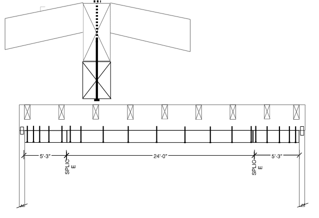
The beam I'm trying to retrofit is a 34'-6" long (E) 6x14 simple-spanned ridge beam (no tension ties, vaulted ceiling - holy moly who designed a 34' span wood beam ever). The beam is showing signs of distress and causing issues throughout the roof and home. The beam and surrounding elements creak whenever wind hits the building. When calculated for DL+LL+WL, the beam is significantly overstressed (1.95 DCR).
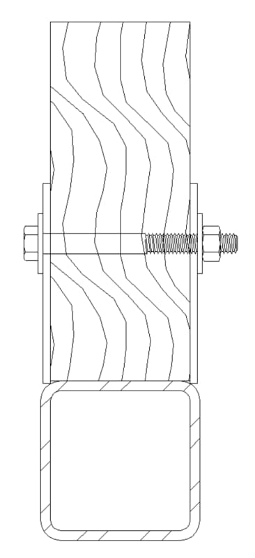
I'm wondering if I can use Dik's HSS with thru-bolt detail from that thread on my dilemma. But to clarify, is that sketch intending to be linear-add strengths, like a vertically stacked sistering, or are the bolts engaging composite action? (Hopefully @Dik will see this)

A 6x20 works when I calc it, so my intent was to build-up a composite section. My initial thought was similar to the other thread's initial idea: Stack another 6x10 directly beneath the existing beam for the middle 24' or so (practical length of getting a new beam into the home), and lag bolt it up into the bottom of the existing beam. Trouble is, VQ/I shows me needing 3/4" lag screws @ 4" OC. This would basically decimate the continuity of tension and compression fibers in the new beam, and cut the tension fibers in the existing beam too. If the lag screws are installed through the bottom, in the center, that's removing approximately 14% (0.75in/5.5in) of the fibers. I don't think I like essentially carving a channel out of the middle of both beams. Plus installing 16" long lag screws straight up is no easy construction task.
The complexity with retrofit comes with the length of the existing - just purchasing a new wood piece 34' long would be a challenge, let alone getting it into the building. So a partial reinforcement of the length seemed prudent, then fill in the sides to make it look continuous. It's a high-value custom home with ocean view about 1mile downhill, so ofcourse the clients don't want anything unsightly in their vaulted ceiling like post-tension cables and struts.
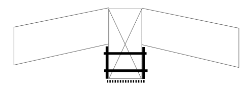
But if I could do it out of steel like that sketch, the contractor could field splice-weld the tube steel and bracket element together into a single 34' long piece, and lift it into place.
My question @Dik for your sketch - if it is intended to make this composite, how do I calculate the force flow transfer through the thru-bolts in your sketch above? If it's just linear add EI strengths, then the bolts are just enforcing vertical compatibility transferring the uniform load down to give the tube steel its portion (similar to what's discussed here:
If you folks have any other ideas for this retrofit, I'm all ears. Thanks in advance!
My post is a similar problem to this one that I found: But I didn't want to hijack his thread with my specific situation.
The beam I'm trying to retrofit is a 34'-6" long (E) 6x14 simple-spanned ridge beam (no tension ties, vaulted ceiling - holy moly who designed a 34' span wood beam ever). The beam is showing signs of distress and causing issues throughout the roof and home. The beam and surrounding elements creak whenever wind hits the building. When calculated for DL+LL+WL, the beam is significantly overstressed (1.95 DCR).
I'm wondering if I can use Dik's HSS with thru-bolt detail from that thread on my dilemma. But to clarify, is that sketch intending to be linear-add strengths, like a vertically stacked sistering, or are the bolts engaging composite action? (Hopefully @Dik will see this)

A 6x20 works when I calc it, so my intent was to build-up a composite section. My initial thought was similar to the other thread's initial idea: Stack another 6x10 directly beneath the existing beam for the middle 24' or so (practical length of getting a new beam into the home), and lag bolt it up into the bottom of the existing beam. Trouble is, VQ/I shows me needing 3/4" lag screws @ 4" OC. This would basically decimate the continuity of tension and compression fibers in the new beam, and cut the tension fibers in the existing beam too. If the lag screws are installed through the bottom, in the center, that's removing approximately 14% (0.75in/5.5in) of the fibers. I don't think I like essentially carving a channel out of the middle of both beams. Plus installing 16" long lag screws straight up is no easy construction task.
The complexity with retrofit comes with the length of the existing - just purchasing a new wood piece 34' long would be a challenge, let alone getting it into the building. So a partial reinforcement of the length seemed prudent, then fill in the sides to make it look continuous. It's a high-value custom home with ocean view about 1mile downhill, so ofcourse the clients don't want anything unsightly in their vaulted ceiling like post-tension cables and struts.
But if I could do it out of steel like that sketch, the contractor could field splice-weld the tube steel and bracket element together into a single 34' long piece, and lift it into place.
My question @Dik for your sketch - if it is intended to make this composite, how do I calculate the force flow transfer through the thru-bolts in your sketch above? If it's just linear add EI strengths, then the bolts are just enforcing vertical compatibility transferring the uniform load down to give the tube steel its portion (similar to what's discussed here:
If you folks have any other ideas for this retrofit, I'm all ears. Thanks in advance!


