Continue to Site

Eng-Tips is the largest engineering community on the Internet

Intelligent Work Forums for Engineering Professionals

  • Congratulations GregLocock on being selected by the Eng-Tips community for having the most helpful posts in the forums last week. Way to Go!

retrofit of old condenser pump: 70 meter head to 30 meter head 5

Status
Not open for further replies.

moideen

Mechanical
May 9, 2006
360
Dear guys,
What is the best way on following conditions?
The 13-year-old condenser centrifugal end suction pump (70-meter head (230 fthd), 1350 gpm) serving for 530-ton centrifugal chilled water system, recently found it is oversized and then we decided to retrofit with new pump. Prepared new isometric drawing with exact measurement and found the actual required head is 31 meters that gives 40-meter difference from existing. Site team had witnessed number of winding damages in past years. sure, the pump was working away from BEP. In this situation raised two opinion
First, install VFD for reducing the head and kw consumption
Second, retrofit with new pump, high energy class motor IE4 AND more efficient pump with 30-meter head and 43 kw input power
I preferred 2nd option and replaced.
Working conditioning is good and perfect, and work at BEP. Before it was drawing 186 amps, now draws only 75 amps only.
But raised some comment from some circles that if VFD fitting for old pumps can achieve the same performance. I opined that two points that
1) VFD is good if the system head and pump head intersect at BEP, then vfd is suitable
2) Being the head difference is large, then replacement is the best option
3) New motor comes with IE4 class premium efficiency instead the old pump IE1
what are your opinions. Thank you
 
Replies continue below

Recommended for you

In order for VFD to be utilized with economic benefit, the system operation must have variable flow requirements. Systems that operate within +/- 10% of BEP flow rates should generally not need VFD. Roughly stated, long periods of operation, maybe 30-50% of all operating time, at flow rates >25% away from BEP could favour a VFD.

Additionally systems that operate at more or less constant head should again NOT usually be fitted with VFD.

In addition to the above, the best systems to use VFD will also have head requirements that are always proportional to flow squared. The system curve will be parabolic.

Thus #1 VFD at BEP head is not good. Actually, the opposite. When the operation mode is a nearly constant flow at a nearly constant head, a constant speed pump should be first choice.

Constant speed pumps, or several pumps in parallel are usually preferred to meet variable flow requirements at constant head. Why, because your operation is basically one or two flow rates, but at constant head.

Delivering a single flow rate at only one or two heads may favour several pumps arranged in series.

Control valves are often used in constant speed pumps to enable operation at relatively minor variations in flow +/- 30% of BEP at relatively minor variations of head, also +/- 30%. Those percentages may vary.

I generally do not like to use control valves with VFD, as the two can set up a conflict of control.

It appears that you have made the correct choice with your selection of the constant speed, no VFD option.


@1503-44: My technical view that the VFD is not fit or consistent when the pump curve and system curve intersect away from BEP, because when reducing the system curve during the time of speed reduction, the efficiency curve will still be kept in same low efficiency area. Am I correct?
So, the selected pump’s control panel has two option, one vfd and next star delta. During peak load pump may work with star delta to prevent the drive loss and will work with VFD at part load condition.
Thank you
 
No because BEP changes with changes in rpm. The same efficiency as at rated BEP rpm and flow conditions tends to follow the new rpm. A good part of pump efficiency and BEP location is derived from having flow into the pump matching the same rate that the impeller is carrying the flow through the pump. Hence when the impeller speed is reduced, it tends to still match the reduced flow going into the pump inlet, so in effect most of the pump's efficiency at rated BEP is maintained at any rpm. Pump efficiency won't change that much. It will be more or less constant at any rpm. That is the advantage of VFD speed control. Keeping a good match between inlet flow and impeller flow is efficient. Flow in does not stall against the impeller, but is carried through the pump in a smooth manner. And at lower rpm, fluid velocity is less, so friction is reduced inside the pump, hence pump efficiency may actually increase a bit as well. The pump efficiency curve mostly scales with flow. In effect you are always at rated BEP efficiency with any flow.

 
1503-44 - good post, clear, spot-on -- star material.

It is a capital mistake to theorise before one has data. Insensibly one begins to twist facts to suit theories, instead of theories to suit facts. (Sherlock Holmes - A Scandal in Bohemia.)
 
Thanks Artist. [thumbsup2]

The only disadvantages are that VFD of course adds a bit more to cost, a compatible motor is required and adding the VFD itself may decrease overall BEP efficiency by a relatively small 3 to 5%. But those effects can be well worth that small eff drop, if you pump a lot of time at flow rates below 20% of rated flow and the reduced rpm will still provides the head you need. At lower flow rates, due to that lesser friction, pump efficiency may increase just enough to counter the VFD 3% loss, maybe a bit more.

 
Agreed, if you can match flow / head at reduced speed for lengthy periods of operation, you are probably well in front due to reduced power and maintenance costs.

It is a capital mistake to theorise before one has data. Insensibly one begins to twist facts to suit theories, instead of theories to suit facts. (Sherlock Holmes - A Scandal in Bohemia.)
 
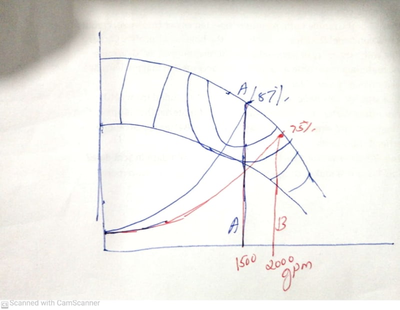
@1503-44;Thank you for the comment, I agree with you the point explained, but I afraid you misread my argument. I pointed the condition that ‘away BEP’, I mean that the oversized pump’s system curve moved to right side of pump curve, the area of low efficiency and cavitation. When goes to my first post, when the oversized pump work with ‘AWAY BEP’ condition and a new VFD fitting to this pump as part of reducing the head and flow, in this situation the system curve kept in low efficiency circle though the flow is reduced. for example, look at the hand sketch of curve A, at BEP, the pump is working at/around 87% efficiency always when VFD is reducing the flow rate. Curve B, the oversized pump is also reducing the flow with VFD at 75% efficiency
curve_kkjmox.jpg
 
Welcome to the real world of pump selection, to alter the pump performance you can either reduce the impeller diameter or the pump speed to suit your duty, the power, efficiency, NPSHa at the new duty point are out of your control - - if unacceptable, change to a pump suitable to the duty.

It is a capital mistake to theorise before one has data. Insensibly one begins to twist facts to suit theories, instead of theories to suit facts. (Sherlock Holmes - A Scandal in Bohemia.)
 
OK. I see what you mean.

Of course when your system curve does not intersect the pump's BEP region, results of installing a VFD will not be ideal. In your example you would indeed have an efficiency of 75% at every rpm. I wouldn't say a VFD is not necessarily a good solution however. If you wanted to operate that pump on the red system curve B, but at a flow rate of 1500gpm and a head close to 60% of the pump's rated speed head, then installing a VFD would let you do that at 75% efficiency -3% eff for the VFD loss = 72% eff. That's not 87%, but still not all that bad. VFD is one option. Let's see what else we could do.

Looking at other options, you could also operate at that same 1500gpm, 60% head point by using a constant speed pump fitted with a control valve and it looks like you can probably get close to 75% efficiency, so that would have the same or even a slightly greater benefit than using a VFD would have. Great, now we have two viable options. We should probably now look at the capital costs of each one, see if we have electric power available there, room within the pipe configuration for a control valve and also evaluate maintenance and operation implications. Let the results of the study determine your selection.

In your example we see that there is no clear cut advantage, both VFD and CV could be viable options. Looking at the point of intersection of the constant speed pump curve and the red system curve B of that example, it shows a flow rate that is roughly 20 to 25% away from the constant speed BEP flow rate. Now remember what I said in my first answer to your post. Systems that operate within +/- 10% of BEP flow rates should generally not need VFD. Roughly stated, long periods of operation, maybe 30-50% of all operating time, at flow rates >25% away from BEP could favour a VFD..

Your example falls right on that border line. Q of around +20% -25% rated BEP. So I would probably recommend a CV in that case, if I had room in the pipe configuration to install it.

A VFD isn't a magic box, so it won't fix a bad pump to system curve match. Sometimes you just have to change the pump impeller, or the whole pump itself.


@1503-44-"Of course when your system curve does not intersect the pump's BEP region, results of installing a VFD will not be ideal"- now we are on the same pitch. this was the content of ours chat. thank you very much
 
That's the only pitch. Its difficult to fix the wrong pump selection. You can only chose the best option to live with it. That could be a VFD or a CV. Do the study and pick your poison. However just saying a VFD is unfit for that situation in all circumstances isn't exactly correct. It may be your best option, maybe not.

 
Depending on the location, are there wide variations in cooling water temperature? Using a VFD anyway to achieve the optimal Delta T across the condenser may well be of benefit in some situations, particularly as significant energy savings may be realized during winter conditions.

CR

"As iron sharpens iron, so one person sharpens another." [Proverbs 27:17, NIV]
 
moideen, are you still there, how about advising on a flow rate and head - from here we might make some sense of it all.

It is a capital mistake to theorise before one has data. Insensibly one begins to twist facts to suit theories, instead of theories to suit facts. (Sherlock Holmes - A Scandal in Bohemia.)
 
From your description of the problem a using the same pump with a smaller impeller should work? Unless you also want to improve process control and get rid of a control valve then i dont see the need for a VFD? The large motor is an advantage. If the pumop is operating aganst a fixed head (e.g. mostly static or because it pumps to a system with a higher pressure the VFD will seldom be a profitable choice wrt to energy savings. But they provide good process control in all cases.

You might be able to get a new impellar or get the existing modified.

Be carefull when considering the VFD because the motor might not be suited. The the cooler is a fan attached to the motor shaft then it might not cool sufficiently at low speeds. The motor cooling fan needs to be on its own motor.

Best regards, Morten
 
crshears: Yes, when the chiller load is coming down to 50%, using VFD is beneficial, the newly installed pump is VFD control and shall be integrated with building automation.
 
@Artisi: Can you elaborate the question? Sorry, I cant catch your point..
 
You are asking about fitting a vastly oversized pump to an application and how to meet a new duty point, if you give an idea of the required flow and the expected head, we stand a chance of making some considered suggestion on speed, impeller dia. etc that might assist your question.

It is a capital mistake to theorise before one has data. Insensibly one begins to twist facts to suit theories, instead of theories to suit facts. (Sherlock Holmes - A Scandal in Bohemia.)
 
@Artisi: The design flow rate is 1530 GPM with 110ft, 45 kW motor, draws 75 amps (346 m3h with 70-meter HD). The old replaced pump was working with 1720 GPM with 90 kW motor, ampere draws 186A.
The ampere difference between the old pump and the new pump is 111A, also the pump is now working at BEP. pls look at the attached curve
 
 https://files.engineering.com/getfile.aspx?folder=5d636ca5-7083-44c8-a54e-6fa0995a60d9&file=1530gpm@110ft.pdf
Status
Not open for further replies.

Part and Inventory Search

Sponsor