Eng-Tips is the largest engineering community on the Internet

Intelligent Work Forums for Engineering Professionals

Reuse a step up Delta-Wye XFMR for a step down Wye-Delta application?

Status
Not open for further replies.

majesus

Electrical
Aug 16, 2007
262
0
0
SA
Hello,

We have a 1.5MVA XFMR that was used to step up 600V to 4160V for an undergrounded (U/G) tunnel in a remote mining operation. The U/G tunnel has been decommissioned and I would like to reuse this transformer for a 4160/600V step down application. However, I am not familiar with a Wye-Delta configuration and I would like feedback or suggestions to avoid any potential pitfalls or problems that might occur with my idea. I have made a quick hand sketch of the Single Line Diagram I would like to implement:

4160VSTEPDOWNXFMR.jpg


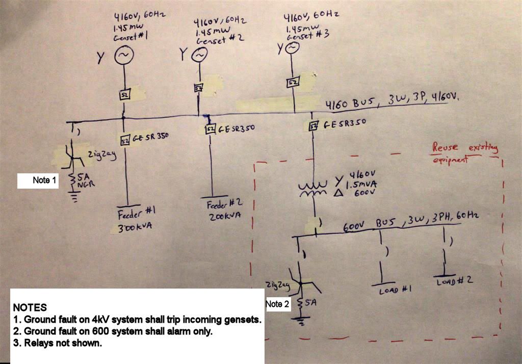
The transformer shall be reused to step down 4160 to 600V as shown. The transformer comes with a 600V bus and several load side distribution feeders. This equipment is shown within the red dotted square. All 600V equipment shall be 3phase, 3 Wire loads.

The connection from the 4160V bus to the transformer primary shall be with a 100m 4kV cable. Primary protection of the 1.5MVA XFMR is a GE SR-350 relay. Secondary protection shall be a 600V Cutler Hammer Magnum air breaker. All protection shall be dialed to 125% of FLA. Primary and secondary voltage systems are resistant grounded via Zigzag transformers.

I was wondering if I could make use of the is Wye to Delta transformer? I have search through the Eng Tips forum and have read Waross comment’s about the reasons why Wye to Delta transformers should not be used on Overhead lines.


However in this application, I have circuit breakers with a digital relay (no single phase fuse disconnects) and I do not need the Line to neutral voltage. (It shall remain disconnected).

Furthermore, from the book Second Edition, Electrical Machines with Matlab by Turan Gonen:

In the Wye-Detla connection, there is no problem with third harmonic components in its voltages, since they are aborbed in a circulating current on the delta side. This connection can be used with unbalanced loads.

Just to note that I do prefer using the conventional Delta-wye step down XFMR, but this application reuses an existing piece of decommissioned equipment.

Thanks for the help.
Majesus
 
Replies continue below

Recommended for you

There are some pitfalls using a wye:delta connection on a distribution circuit. The issues may not be as serious in your application.
The root of the problem is the delta connection and the relatively low impedance of distribution transformers.
When you draw a delta vector sketch, the delta must close. If there are any line to neutral voltage differences or phase angle errors on the primary circuit the delta won't close. But you have bolted it closed anyway. The result is a heavy circulating current at such a phase angle as to cause a voltage drop in the higher voltage phase(s) and a voltage rise in the lower voltage phase(s).
Unfortunately such unbalances are common on long distribution circuits with many distributed single phase loads.
When you add voltage regulators to the mix the situation gets worse.
If the voltage is 5% low on two phases and 10% low on one phase coming into a set of single phase voltage regulators the outgoing line to neutral voltages may be equal but the phase to phase voltages will not be equal. The result is phase angle errors and the delta does not close.
Now if one voltage regulator "hangs up" while the other two remain functional you may lose your transformer. I lost two of a three transformer bank when some idiot changed my wye:wye connection to a wye:delta connection on an installation a long way out of town on a circuit with a faulty voltage regulator.
The other option is to float the wye point. This works well once it is energized but you may experience 173% voltage switching transients getting the transformer on-line.
In your case the voltages and the phase angles should be well balanced.
I don't see the impedance for your transformer. I expect that it will be between 5% and 10%. That is in your favor. We see lower impedances on some distribution transformers. (In the case of the failed transformers the utility penalized poor efficiency transformers and the impedance was quite low.)
I would connect the wye point solidly to the neutral of the system (not ground). If the wye point is floating, when one phase winding saturates at 25 x FLC the other phases may experience overvoltage transients.
The impedance required to stabilize the wye point voltage at 25 X FLC may be so low that the 100M of connection cable will be enough impedance.
Most of the conditions that cause issues in distribution lines are not a factor in your installation. However I would monitor the temperature of the transformer and see how the temperature correlates with the load current for a while.
Either a wye:delta or a delta:wye connection does a better job of distributing unbalanced loads onto the generator than a wye:wye connection.
Personally I would try the wye:delta arrangement in a similar situation. I would monitor the transformer for overheating.
If circulating currents became an issue I would look for a contactor able to withstand the transformer inrush (possibly with all three poles in parallel) and install it in the connection from the wye point to the system neutral. I would arrange the contactor to close just before the transformer was energized and open a few seconds after the inrush had decayed.
That will avoid energization transients and then, when the contactor has opened, avoid circulating currents.
But stand by for suggestions from others.
Yours
Bill

Bill
--------------------
"Why not the best?"
Jimmy Carter
 
An unsolicited suggestion:
I see that you are using zig-zag transformers for grounding.
Have you considered using the infamous wye:delta configuration to advantage?
For a 5 Amp current at 600 Volts, you need a 3 KVA transformer.
Three 600 Volt primary dry type transformers connected in wye:delta with a suitable resistor from the wye point to ground will provide similar grounding to the zig-zag transformer and may be cheaper and will certainly be more readily available. The secondary voltage is not really that important.

Bill
--------------------
"Why not the best?"
Jimmy Carter
 

Thanks Waross, I knew you would answer ;)
I appreciate your help.

This is an industrial off the grid site. The 4kV system should be well balanced. The Wye-Delta XFMR has a Z=5.8%, also to note it is an oil type, 3 phase XFMR. It shall be wired for temperature monitoring.


I do not have a true 4160V system neutral other than the neutral side of the Zigzag which is connected to the 5A NGR. I was going to float XFMR's primary wye neutral. You mentioned that when energizing, "If the wye point is floating, when one phase winding saturates at 25 x FLC the other phases may experience overvoltage transients." What is the "typical" duration of the 25xFLC? (Nuisance trips). Also for the overvoltage transients on the primary. I assume this is VL-N. Is this a major concern? Would this cause a cable or XFMR failure?


To answer your questions about the zigzag XFMRs, they are already existing. No new equipment is being bought.

Regards,
Majesus
 
Curious... Shouldn't the zig-zag on the 600V (Delta) side be connected directly to the main transformer without CB's and not from the bus as a "feeder"?
 
It is commonly done like this. It provides an easy way of connecting the Zigzag onto the system. Also notes that the Canadian Electrical Mines Act requires that the Zigzag Circuit breaker be monitored and if it disconnects, it must de-energize the system. (This is not shown on my SLD.)

 
Sort of to the point, but, why or why don't you think it will work? What is your concern?

Normally I would be concerned about a delta system, but at such low voltages, I believe most wireing should be able to stand the offset of a phase to ground fault on an adjacent phase.

The problem with this configuration is if you have to little zero sequence source, you can't determine the location of a phase to ground fault. (Not fun as you start a fire in the forrest).
 
@majesus, sorry to branch off on your topic. That's Canada... fair enough. I was wondering as we have a substation in Southern Africa where the zig-zags were connected as you depict with interlocking to the main transformer LV busbar CB then the wiseguys with thick glasses came and insisted the zig-zag must be connected as near as possible to the main trafo's LV connections i.e. upstream of the trafo busbar LV CB. Same thing really, eliminates the need for extra CB and control wiring to monitor status of zig-zag CB.
Just an idea.
 
Zigzags do not have to be as close as possible. (Unlike surge arrestors.) As you know, Zigzags are used to establish a ground point so that we can monitor ground faults on the system. They and are not required in extreme proximity to the main XFMR.

 
I would consider connecting the transformer primary wye point to the neutral point of the zig-zag transformer, not to ground. Only if heating issues develop would I add a contactor to close the neutral connection while the transformer is being energized.
I have read about and seen a technique used to energize legacy wye delta transformer banks. The three pole mounted transformers are fed by four cutouts. One cutout for each phase and one cutout for the neutral/wye point. When the transformer bank is energized from the field the neutral/wye point cutout is closed first. Then the phase cutouts are closed one at a time. This avoids switching transients.
Then the fuse holder in the neutral/wye point cutout is removed and taken away leaving the wye point floating. This avoids circulating current issues.
The over voltage transient is related to the energization surge.
For the sake of simplicity consider a bank of three transformers connected wye:delta with a floating wye point. Close a cutout on one phase and nothing happens. Close the cutout on the second phase and two transformers are energized in series. Now tink about the residual magnetism. If it happens that the residual in one transformer is in the same direction as the that transformer may saturate and we have the typical low impedance that may result in the 25 X I in a single transformer. However if the other transformer which is in series has residual flux in the opposite direction to the flux generated by the energizing current then secondary over voltages may occur. It gets a little more complex when three phases are energized simultaneously but you get the idea.
I hope this helps.

Bill
--------------------
"Why not the best?"
Jimmy Carter
 
Status
Not open for further replies.
Back
Top