APG817
Civil/Environmental
- Aug 13, 2018
- 12
Hello Psmart,
I've been working on a couple residential stormwater detention designs, and some of them feature reverse flow conditions.
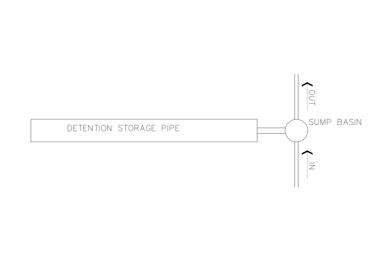
Traditionally we would have the site drainage in a 6-inch pipe and this would enter into the uphill side of our Detention Storage Pipe.
The Detention Storage Pipe would then flow linearly into a Basin with either a metering orifice or a sump pump.
For this particular case we have a Basin with sump pumps. Connected to the Basin is our Detention Storage Pipe. The design intent is to have water enter directly into the basin, and then be allowed to 'back-up' into the Detention Storage Pipe. Over the storm duration we would expect to see the elevation rise in the Detention Pipe, and then decrease over time as the Detention empties.
What I'm trying to analyze is how large of a diameter is needed for the pipe connecting the Sump Basin and the Detention Pipe. In other words, will the storm runoff be able to effectively 'equalize' between the basin and detention pond using a 6-inch, 10-inch, 24-inch, etc. Assuming that the Detention Pipe is approximately 36-48" inner diameter. In the past we have simply made the assumption that the water levels are able to equalize, but I'm trying to illustrate that it is not always a safe assumption.
For larger storms, I would expect that a smaller diameter pipe like a 6 or 8-inch connection might actually be a limiting factor in equalizing between a basin and a 48-inch detention pipe. In this sense, it would make the most sense to have the connection be as close as possible to the diameter of the detention pipe. However, I can't seem to get the reverse flow aspect properly entered in the model. The model is attached for reference.
I followed the instruction at Link which says,
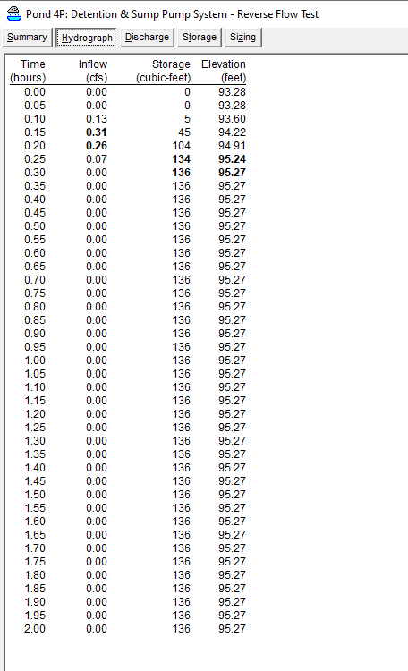
In my model, I have a Basin with Secondary 6-inch culvert outlet defined. The culvert has a negative slope, but when I drag it to the Detention Pipe, no double-ended arrow appears, just a normal one-way arrow. From the Detention Pipe results table it shows that water is entering the Detention Pipe, but never exiting back through the culvert to the basin.
I could add a 6-inch culvert outlet BACK from the Detention Pipe to the Basin, but then my concern is that the model thinks there are (2) separate 6-inch lines. One going in, and one coming back, when in reality there is just a single shared pipe.
Please let me know your thoughts and what I could be doing wrong.
Thank you,
I've been working on a couple residential stormwater detention designs, and some of them feature reverse flow conditions.
Traditionally we would have the site drainage in a 6-inch pipe and this would enter into the uphill side of our Detention Storage Pipe.
The Detention Storage Pipe would then flow linearly into a Basin with either a metering orifice or a sump pump.
For this particular case we have a Basin with sump pumps. Connected to the Basin is our Detention Storage Pipe. The design intent is to have water enter directly into the basin, and then be allowed to 'back-up' into the Detention Storage Pipe. Over the storm duration we would expect to see the elevation rise in the Detention Pipe, and then decrease over time as the Detention empties.
What I'm trying to analyze is how large of a diameter is needed for the pipe connecting the Sump Basin and the Detention Pipe. In other words, will the storm runoff be able to effectively 'equalize' between the basin and detention pond using a 6-inch, 10-inch, 24-inch, etc. Assuming that the Detention Pipe is approximately 36-48" inner diameter. In the past we have simply made the assumption that the water levels are able to equalize, but I'm trying to illustrate that it is not always a safe assumption.
For larger storms, I would expect that a smaller diameter pipe like a 6 or 8-inch connection might actually be a limiting factor in equalizing between a basin and a 48-inch detention pipe. In this sense, it would make the most sense to have the connection be as close as possible to the diameter of the detention pipe. However, I can't seem to get the reverse flow aspect properly entered in the model. The model is attached for reference.
I followed the instruction at Link which says,
Sim-Route Modeling said:For example, if you have pond P1 that normally flows into pond P2, you would define the reverse outlet in pond P2, and set the device routing to "Secondary". (If the device is a culvert, this means it will have a negative slope, and the entrance loss (Ke) applies to any flow entering the "lower" end of the pipe.) On the routing diagram, drag the secondary outflow handle back to P1, causing a double-ended arrow to appear.
In my model, I have a Basin with Secondary 6-inch culvert outlet defined. The culvert has a negative slope, but when I drag it to the Detention Pipe, no double-ended arrow appears, just a normal one-way arrow. From the Detention Pipe results table it shows that water is entering the Detention Pipe, but never exiting back through the culvert to the basin.
I could add a 6-inch culvert outlet BACK from the Detention Pipe to the Basin, but then my concern is that the model thinks there are (2) separate 6-inch lines. One going in, and one coming back, when in reality there is just a single shared pipe.
Please let me know your thoughts and what I could be doing wrong.
Thank you,