Eng-Tips is the largest engineering community on the Internet

Intelligent Work Forums for Engineering Professionals

Reverse Whitworth Quick Return Mechanism 3

Status
Not open for further replies.

Kyza3000

Mechanical
May 30, 2024
5
0
0
AU
I am trying to make a sort of reverse Whitworth Quick Return Mechanism in which I am converting this oscillating arm movement into a rotational movement rather than the other way around, it looks like the mechanism should work in reverse however in practice the oscillating arm just pushes the rotating wheel back and forth rather than doing a full rotation as seen in the gif. Any ideas on how I can make this work?
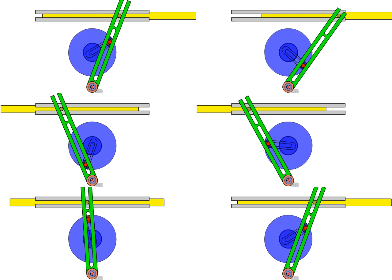
Whitworth-Quick-Return-Mechanism_whv3ej.gif
 
Replies continue below

Recommended for you

You need to get past the dead spots. Either:

The disk needs enough inertia to get itself past the dead spot, like the big flywheel of a single cylinder steam engine.

Or

Two identical mechanisms working out of phase
 
Perhaps another green arm at the back, driven by another red pin at the back a few degrees different to the front one. Then another brown pin adjacent to the one shown but at the rear with the new arm still pivoting on the orange bearing? The blue disc would have a bearing on its perimeter and not in the centre to allow access from both sides.
 
I think out-of-phase won't work to eliminate dead spots because the rate of rotation is tied to one linear motion. It works on steam locomotives because the two pistons are independent, which won't be the case here.

Perhaps a cam to nudge the wheel at the dead spots? Then one might need a clocking mechanism as the two positions require mirror image cams.
 
Lose the short arm + pivot. Attach the end of the green arm to the axle via a sprag clutch. This will give drive in one direction only. For drive in both directions repeat at the rear adding an idler gear to reverse the direction and keep it the same direction as the front arm. The next level is for the two arms drive forwards in both directions. They both have a direct drive via a sprag clutch plus an idler gear train adjacent to the direct drive. This is mirrored on the rear.

Here is a link to a push and pull propulsion where both levers drive forwards on the push and pull strokes and can be used independently too.

 
" What is driving tour linear motion? This mechanism is designed for sinusoidal motion. Is that what you have? "

I may have misunderstood the original post. I assumed that the driven linear motion of the yellow rod needed to be converted into rotary motion. So reciprocating the yellow rod would drive the green arm +/- 45 degrees via the brown pin in the slot in the green rod. The green rod would continually index the axle clockwise on both the forward and return stroke of the yellow rod.
 
You can use a sprag clutch. but the whitworth motion isn't symmetrical. I am not sure why the OP wants it, but in one direction the rod moves slower than it moves in the other direction, but a reverse mechanism from that would drive the wheel at a constant speed; a clutch arrangement won't do that.
 
Does the op wants the reciprocating top rod to drive the axle?
Is the reciprocating rod speed rising and falling during the strokes? I guess it has to.
Do they need a constant speed at the axle or is it acceptable to also rise and fall as the input speed rises and falls?
 
Sorry for the late reply, the mechanism will be driven by the sinusoidal motion of the green arm, and ideally it will cause the axle to rotate at a constant speed without the "quick return", I had considered a using two, 1 way bearings similar to what was suggested but my main concern was that the fast rotation and relatively high torque of my system would cause significant wear on the clutches. As a result I tried to find a mechanism that might be slightly less prone to wear. I am no engineer and am just messing around with an idea I had a while ago, i have no idea how wear resistant the clutches will be, so I think I'll give it a go.

Thankyou for all replies :D
 
You will undoubtedly have speed variations. This is due to the variation in geometry (swing arm radii) as the linkage components go through their paths. The only way to achieve semi-consistent rotary speed from reciprocating linear motion is with a rack and pinion. Include sprag clutches in your arrangement to achieve consistent rotary motion from reciprocating linear motion.
 
Well it looks like you are replicating my lever drive wheelchair motion I posted earlier. You will see on the video that when only using one lever the wheels spin forwards on the push and pull. With the gearbox mirrored on the other independent lever. This enables the occupant to pull on one and push on the other giving a neutral seating position not being pulled forwards or pushed backwards. Or course both levers can be moved in tandem if this suits you. I may have the original .dwg files of the lever gearboxes if you want them.
 
Hi Kyza3000

I have found the .dwg file for the wheelchair lever drive mechanism. It does include the complete drivetrain including the CVT & differential. You will need to isolate the various layers to see the location of the sprag clutches. Each drive lever is completely independent from the other. They both drive in both directions and both drive the mid shaft in the same direction & then onto the CVT & onto the differential gearbox & then independently to the wheels.
I don't know how to send the file directly to you, if you can post the way this can be done via the forum without posting email addresses.
 
Hmm, that is a bit of a problem. I am comfortable sharing an old email if you would be willing to send it to me through that, you would not have to publicly share your email however I would be able to see it when I go to download the file. Another option would be to convert it to a link that I could click on and download the file from there using a website like "weshare.com", I know it's not the most secure method, and the link would have to be posted here making it publicly available, but other than that I am drawing a blank on any other methods, I completely understand if you'd rather not share for privacy reasons and am very appreciative of the offer anyway.
 
Status
Not open for further replies.
Back
Top